
DIAGNOSIS PROCEDURE |
STEP 1. M.U.T.-III data list |
|
Q.
Is the check result normal?
|
 Intermittent
malfunction (Refer to GROUP 00 - How to Use
Troubleshooting/Inspection
Service Points Intermittent
malfunction (Refer to GROUP 00 - How to Use
Troubleshooting/Inspection
Service Points ) ) |
|
 Go to Step 2
. Go to Step 2
. |
|
STEP 2. Check for stationary steering effort (Refer to
|
Q.
Is the check result normal?
|
| Go to Step 3
. |
|
| Repair. |
|
STEP 3. Connector check: B-20 power steering fluid pressure sensor connector |
 |
Q.
Is the check result normal?Go to Step 4
.Repair or
replace. |
STEP 4. Perform voltage measurement at B-20 power steering fluid pressure sensor connector. |
|
Q.
Is the check result normal?Go to Step
10 .Go to Step 5
. |
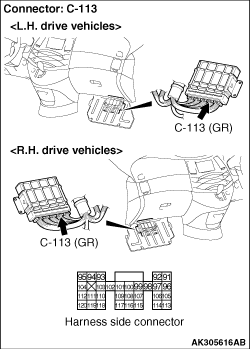
STEP 5. Perform voltage measurement at C-113 engine-ECU <M/T> connector or engine-A/T-ECU <A/T> connector. |
 |
Q.
Is the check result normal?Go to Step 6
.Go to Step 7
|
STEP 6. Connector check: C-113 engine-ECU <M/T> connector or engine-A/T-ECU <A/T> connector |
|
Q.
Is the check result normal?
Repair or
replace. |
STEP 7. Connector check: C-113 engine-ECU <M/T> connector or engine-A/T-ECU <A/T> connector |
|
Q.
Is the check result normal?Go to Step 8
.Repair or
replace. |
STEP 8. Check harness between B-20 (terminal No. 3) power steering fluid pressure sensor connector and C-113 (terminal No. 97) engine-ECU <M/T> connector or engine-A/T-ECU <A/T> connector. |
|
Q.
Is the check result normal?Go to Step 9
.Repair. |
STEP 9. M.U.T.-III data list |
|
Q.
Is the check result normal?
|
| Intermittent
malfunction (Refer to GROUP 00 - How to Use
Troubleshooting/Inspection
Service Points ). |
|
| Replace engine-ECU
<M/T> or engine-A/T-ECU <A/T>.
|
|
STEP 10. Perform resistance measurement at B-20 power steering fluid pressure sensor |
|
Q.
Is the check result normal?Go to Step
13 . Go to Step
11. |
STEP 11. Connector check: C-113 engine-ECU <M/T> connector or engine-A/T-ECU <A/T> connector |
|
Q.
Is the check result normal?Go to Step
12 .Repair
or replace. |
STEP 12. Check harness between B-20 (terminal No. 1) power steering fluid pressure sensor connector and C-113 (terminal No. 96) engine-ECU <M/T> connector or engine-A/T-ECU <A/T> connector. |
|
|
|
Q.
Is the check result normal?Go to Step 9
.Repair. |
STEP 13. Perform voltage measurement at C-112 engine-ECU <M/T> connector or engine-A/T-ECU <A/T> connector. |
 |
Voltage rises (Steering wheel: Operated) Q.
Is the check result normal?Go to Step
17 .Go to Step
14 . |
STEP 14. Connector check: C-112 engine-ECU <M/T> connector or engine-A/T-ECU <A/T> connector |
|
Q.
Is the check result normal?Go to Step
15 .Repair
or replace. |
STEP 15. Check harness between B-20 (terminal No. 2) power steering fluid pressure sensor connector and C-112 (terminal No. 84) engine-ECU <M/T> connector or engine-A/T-ECU <A/T> connector. |
|
Q.
Is the check result normal? Go to Step
16 .Repair. |
STEP 16. Check harness between B-20 (terminal No. 3) power steering fluid pressure sensor connector and C-113 (terminal No. 97) engine-ECU <M/T> connector or engine-A/T-ECU <A/T> connector. |
|
Q.
Is the check result normal? Replace power
steering pressure sensor.Repair. |
STEP 17. Connector check: C-112 engine-ECU <M/T> connectors or engine-A/T-ECU <A/T> connector |
|
Q.
Is the check result normal? Go to Step 9
.Repair or
replace. |