|
|
Input signal from the ignition
switch (ACC) is used to operate the functions below. If
the signal is abnormal, these functions will not work
normally.
|
|
|
- Seat belt warning buzzer function
- Door-ajar warning buzzer function
- Sunroof timer function
- Windshield wiper and washer
- Rear wiper and washer
- Electric retractable remote controlled
mirror
- Interior lamp automatic-shutdown function
|
|
|
- Malfunction of the ETACS-ECU
- Damaged harness wires and connectors
|

|
Q.
Is the check result normal?
 Go to Step
2. Go to Step
2.
 Repair
the defective connector. Repair
the defective connector.
|
|
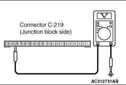
(1)Remove the ETACS-ECU, and
measure at the junction block side.
(2)Ignition switch:
ACC position
|
|
(3)Voltage between C-219 ETACS-ECU
connector terminal No.18 and body earth
OK:
System voltage
Q.
Is the check result normal?
Go to Step
4.
Go to Step
3.
|

|
| note |
Prior to the wiring harness
inspection, check junction block connector
C-202, and repair
if necessary.
|
- Check the power supply line for open
circuit.
Q.
Is the check result normal?
The trouble can be
an intermittent malfunction (Refer to GROUP 00 - How
to Cope with Intermittent Malfunction  ). ).
Repair the wiring
harness.
|
|
|
Check that the ignition switch
(ACC) signal is received normally.
|
|
|
Q.
Is the check result normal?
|
|
|
The trouble can be
an intermittent malfunction (Refer to GROUP 00 - How
to Cope with Intermittent Malfunction ).
|
|
|
|
