
| If it is not in this list: Click |
|
| caution | During diagnosis,
a diagnosis code associated with another system may be set
when the ignition switch is turned
on with connector(s) disconnected. After completing the
repair, confirm all systems for diagnosis
code(s). If diagnosis code(s) are set, erase them
all. |
| M.U.T.-III
screen |
Diagnosis
detail |
Reference
page |
|
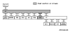
| (The ECUs that
are not adopted are not displayed.) |
Comment |
||
 |
Failure in red
displayed area is estimated. |
Diagnosis Item
1 Communication with no ECUs is possible. |
*1 |
| - |
- |
Diagnosis Item
2*2 Diagnose shorts in the power supply to CAN bus line. |
|
| - |
- |
Diagnosis Item
3*2 Diagnose shorts in the earth to CAN bus line. |
|
| - |
- |
Diagnosis Item
4*2 Diagnose shorts between CAN_H and L lines. |
|
 |
Disconnection in
red displayed area is estimated. |
Diagnosis Item
15 Diagnose when the M.U.T.-III cannot receive the data sent by FCM-ECU. <Vehicles with FCM-LS>. |
|
 |
Disconnection in
red displayed area is estimated. |
Diagnosis Item
16 Diagnose when the M.U.T.-III cannot receive the data sent by steering wheel sensor. |
|
 |
Disconnection in
red displayed area is estimated. |
Diagnosis Item
17 Diagnose when the M.U.T.-III cannot receive the data sent by ASC-ECU. |
|
| note |
|
| If it is not in this list: Click |
|