
|
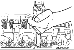
1.Using special tool Valve
spring compressor (MD998735), compress the
spring.
2.Remove the retainer locks.
|

|
Using the special tool Valve stem
seal pliers (MB992085), nip the valve stem seal and
remove it.
|

|
| caution |
- Valve stem seals for inlet valves and
for exhaust valves are
different. Be sure to install the
correct ones.
- Valve stem seal identification
colour.
Inlet:
Grey
Exhaust: Grey
green
|
|

|
Use a special tool to install the
valve stem seal, obeying the following
procedures:
1.The special tool valve stem seal
installer adjustable (MB992677) is composed of the
components shown in the illustration.
1: Chuck
2:
Sleeve
3: Rock nut (small)
4: Outer pipe
5: Rock
nut (large)
6: Guide pin (5.9)
7: Guide pin
(4.9)
8: Cap
|

|
2.Adjust the inside chuck
diameter, obeying the following procedures.
(1)
Install the sleeve to the chuck as shown in the
illustration.
(2)
Install the shoulder of the valve stem seal to the chuck,
aligning with the outer
circumference line of the chuck as shown in the
illustration.
(3)
Turn the sleeve to wring the chuck.
(4)
Stop the sleeve at the position where you can easily remove
the valve stem seal by
hand.
(5)
Use the (small) rock nut to fix the sleeve.
|


|
3.Adjust the stem seal
insertion length, obeying the following procedures.
Set
the valve stem seal insertion length (L) of 18.2mm.
(1)
The position, in which the end face of the outer pipe is
aligned with the outer circumference
line of the chuck, is 0mm of the insertion length. Insert
the chuck and the sleeve into the
outer pipe to fit the nut as shown in the
illustration.
(2)
Turn the chuck to adjust the valve stem seal insertion
length.
|
|
| note |
The insertion
length can change by 1mm per the
chuck turn.
To easily know how
many times the chuck is turned, put
the mark at the position shown
in the illustration.
|
|
(3)
Use a vernier caliper to measure the checkpoint (L1) of the
insertion length shown
in the illustration. Check the insertion length.
(4)
Use the (large) rock nut to fix the sleeve.
(5)
4.Install the cap to the guide pin
(5.9).
5.Install the guide pin (5.9) as shown in
the illustration.
6.Apply the engine oil to the
valve stem seal to set the chuck.
7.Install the
valve spring seat.
|

|
8.Use the plastic hammer to
insert the valve stem seal.
|

|
Install the valve spring end with
its identification colour toward the spring
retainer.
Identification
colour
Inlet: White
Exhaust:
Blue
|
|
Using special tool Valve spring
compressor (MD998735), compress the valve spring and insert
the retainer lock into position.
|

|
1.Check in the following
procedure before reusing the cylinder head bolt.
(1)
Measure the outside diameter "A".
(2)
Measure the smallest outside diameter "B" within the range
"X" shown in the illustration.
(3)
If the difference of outside diameter of thread exceeds the
limit, replace the cylinder
head bolt.
Limit: 0.1mm
|

|
2.
| caution |
Attach the head bolt washer in
the direction shown in the figure.
|
Tighten the bolts in the illustrated sequence two or
three rounds.
Tightening torque: 45 ± 2
N·m
|

|
3.
| caution |
- When the tightening angle
is smaller than the specified tightening
angle, the appropriate tightening
capacity cannot be
secured.
- When the tightening angle is larger than
the specified tightening angle, remove
the bolt to start from the beginning
again according to the
procedure.
|
Using the special tool Angle gauge (MB991614),
tighten the cylinder head bolt another
150°.
|


