
|
1.Using special tool
Flywheel stopper (MD998781), hold the drive plate.
|

|
2.Remove the crankshaft
pulley centre bolt.
| caution |
provide one punch mark on the
head of the crankshaft pulley
centre bolt each time the bolt is removed.
Replace the bolt that already has three punch
marks.
(the evidence of having been tightened three
times)
|
|
|
|
1.Temporarily tighten the
alternator to the alternator bracket.
|

|
2.In accordance with the
tightening order shown in the illustration, tighten the
installation
bolts for the alternator to the specified
torque.
Tightening torque: 47 ± 11
N·m
|
|
1.
| caution |
before installing the
crankshaft pulley centre bolt,
check the number of punch marks on its head.
(the bolt is reusable if it is two or less.) If
the bolt has three punch marks, replace
it.
|
Using special tool Flywheel stopper (MD998781), hold
the drive plate.
|

|
2.Wipe the dirt on the
crankshaft pulley washer using a rag.
3.Using a
rag, wipe the dirt on the crankshaft pulley, the front
flange, the crankshaft
sprocket, the thread hole of the crankshaft and then remove
the grease.
4.Install the front flange and
crankshaft pulley.
5.Apply an appropriate and
minimum amount of engine oil to the threads of crankshaft
pulley centre bolt and lower part of the
flange.
6.Install the crankshaft pulley washer to
the crankshaft pulley centre bolt.
7.Tighten the
crankshaft pulley centre bolt to 110 N·m.
|
|
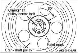
8.Make a paint mark on the
crankshaft pulley centre bolt.
9.Make a paint mark
on the bolt end at a position 60° from the paint mark
made
on the crankshaft pulley in the direction of tightening the
crankshaft pulley centre bolt.
| caution |
- When the tightening angle
is smaller than the specified tightening
angle, the appropriate tightening
capacity cannot be
secured.
- When the tightening angle is larger than
the specified tightening angle, remove
the bolt to start from the beginning
again according to the
procedure.
|
10.Turn the crankshaft pulley centre bolt
another 60° and make sure that the
paint marks on the crankshaft pulley and crankshaft pulley
centre bolt are aligned.
11.Loosen the crankshaft
pulley centre bolt fully.
12.Tighten the
crankshaft pulley centre bolt to 110 N·m.
|
|
13.Make a paint mark on the
crankshaft pulley centre bolt.
14.Make a paint
mark on the bolt end at a position 60° from the paint
mark made
on the crankshaft pulley in the direction of tightening the
crankshaft pulley centre bolt.
| caution |
- When the tightening angle
is smaller than the specified tightening
angle, the appropriate tightening
capacity cannot be
secured.
- When the tightening angle is larger than
the specified tightening angle, remove
the bolt to start from the beginning
again according to the
procedure.
|
15.Turn the crankshaft pulley centre bolt
another 60° and make sure that the
paint marks on the crankshaft pulley and crankshaft pulley
centre bolt are aligned.
|

