
| Item |
2WD |
4WD |
|
| Transmission
model |
F1CJC |
W1CJC |
|
| Torque
converter |
Model |
3-element, 1-stage,
2-phase |
|
| Stall torque
ratio |
1.995 |
||
| Lock-up |
Present |
||
| Transmission
type |
Forward automatic CVT
(steel belt-driven), reverse 1 speed |
||
| Pulley ratio |
Forward |
2.631 -
0.378 |
|
| Reverse |
1.960 |
||
| Final reduction gear
ratio |
6.026 |
||
| Shift
position |
P-R-N-D+6-speed
sport mode (with the paddle
shift) |
||
| Control type |
Electronically-controlled |
||
| Function |
Shift
control |
Present |
|
| Line pressure
control |
Present |
||
| Select
control |
Present |
||
| Lock-up
control |
Present |
||
| Self-diagnosis
function |
Present |
||
| Fail-safe
function |
Present |
||
| Slip control at
start |
Present |
||
| Oil pump |
Model |
Vane-type
pump |
|
| Drive type |
Driven by the engine,
sprocket, and chain |
||
| CVT fluid |
Brand name |
MITSUBISHI MOTORS
GENUINE CVTF-J4 |
|
| Capacity
(L) |
6.9 |
||

 |
|

| Component |
Function |
| Manual
valve |
Distributes the
clutch operating pressure to each circuit, depending
on each selector lever position. |
| Lock-up control
valve |
Regulates the
engagement pressure and disengagement pressure of the
torque converter. |
| Torque converter
regulator valve |
Regulates the
supply pressure to the torque converter to the optimal
pressure for the driving conditions. |
| Pressure regulator
valve |
Regulates the
discharge pressure from the oil pump to the optimal
pressure (line pressure) for the driving
conditions. |
| Secondary reducing
valve |
Reduces the line
pressure to regulate the secondary pressure. |
| Primary reducing
valve |
Reduces the line
pressure to regulate the primary pressure. |
| Pilot valve
A |
Reduces the line
pressure to regulate the operation pressures of
the solenoid valves below:
|
| Pilot valve
B |
Reduces fluid
pressure delivered from pilot valve A to regulate the
operation pressure of the lock-up solenoid valve. |
| Line pressure
solenoid valve |
Controls the
pressure regulator valve. |
| Primary pressure
solenoid valve |
Controls the
primary reducing valve. |
| Secondary pressure
solenoid valve |
Controls the
secondary reducing valve. |
| Lock-up solenoid
valve |
Controls the
lock-up control valve. |
| Select solenoid
valve |
Regulates the
forward clutch pressure and reverse brake pressure. |


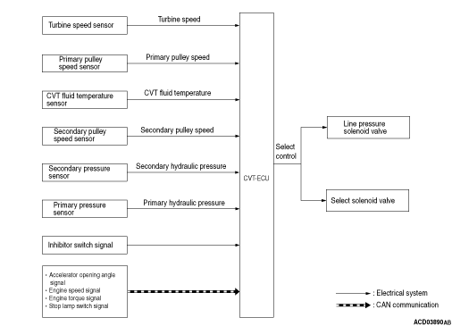
| Item |
Input/output
signal |
Control |
||||
| Shift
control |
Line pressure
control |
Select
control |
Lock-up
control |
Fail-safe
function* |
||
| Input |
Engine torque
signal |
× |
× |
× |
× |
× |
| Engine speed
signal |
× |
× |
× |
× |
× |
|
| Throttle position
signal |
× |
× |
× |
× |
- |
|
| Idle
signal |
× |
× |
- |
× |
- |
|
| Stop lamp switch
signal |
× |
× |
× |
× |
- |
|
| Primary pressure
sensor |
- |
× |
- |
- |
× |
|
| Secondary pressure
sensor |
× |
× |
- |
- |
× |
|
| CVT fluid
temperature sensor |
× |
× |
× |
× |
× |
|
| Turbine speed
sensor |
× |
× |
× |
× |
× |
|
| Primary pulley
speed sensor |
× |
× |
× |
× |
× |
|
| Secondary pulley
speed sensor |
× |
× |
- |
× |
× |
|
| Inhibitor
switch |
× |
× |
× |
× |
× |
|
| Shift switch
assembly |
× |
× |
- |
× |
- |
|
| Output |
Line pressure
solenoid valve |
× |
× |
× |
- |
× |
| Primary pressure
solenoid valve |
× |
× |
- |
- |
× |
|
| Lock-up solenoid
valve |
- |
- |
- |
× |
× |
|
| Secondary pressure
solenoid valve |
× |
× |
- |
- |
× |
|
| Select solenoid
valve |
× |
- |
× |
- |
× |
|
| Selector lever
position display |
- |
- |
× |
- |
- |
|
| note | *: If an abnormal input/output
signal is generated, the CVT-ECU will
trigger a fail-safe function. |
| Item |
Contents |
| Control
content |
When the system
detects a wheel spinning, it will restrict engine
performance and pulley ratio to increase line pressure. The
clutch pressure is also increased. |
| Vehicle behaviour
during control |
The engine speed
and the vehicle speed will not be increased although
the driver continues to depress the accelerator pedal during
a wheel spinning. |
| Resume
condition |
The system resumes
normal operation when wheel spinning is eliminated. |
| Item |
Contents |
| Control
content |
When the CVT fluid
temperature rises, the system will decrease the
maximum permissible shifting speed and torque to avoid
overheat. |
| Vehicle behaviour
during control |
Note that driving
performance may be deteriorated. |
| Resume
condition |
Resumes normal
operation when the CVT fluid temperature drops. |
| Item |
Contents |
| Control
content |
The system
restricts the engine performance in accordance with vehicle
speed when the vehicle is reversing. |
| Vehicle behaviour
during control |
Driving performance
may be deteriorated. |
| Resume
condition |
Resumes normal
operation when the selector lever is moved from R
range to another. |
| Item |
Contents |
| Control
content |
The system will
deactivate the reverse brake when the selector lever
is moved to R range while driving forwards at a certain
speed. |
| Vehicle behaviour
during control |
The transmission
will remain at neutral range although the driver
moves the selector lever to R range while the vehicle is
driven forwards. |
| Resume
condition |
Resumes normal
operation when the vehicle is driven at lower speed.
(The system engages the reverse brake) |