|
|
1.Remove the differential
case assembly, differential side bearing spacer and
differential side bearing.
|
|
|
2.Fix the following special
tools in a vice, and install the differential carrier
assembly.
- Working base (MB990909)
- Working base adapter (MB991116)
|

|
3.Use special tool side
bearing holder (MB992111) to install the differential case
assembly, differential side bearing spacer and differential
side bearing to the differential carrier, then perform the
following checks. Then tighten a flange bolt (M10 × 75
mm)* to the specified
torque.
Tightening torque: 43 ± 7
N·m
| note |
*: equivalent
to part number "MB140473".
|
|

|
1.Set a dial gauge against
the drive gear teeth edge and fix the drive pinion. Rotate
the drive gear to measure the backlash at four or more
points.
Standard value: 0.08 - 0.15
mm
2.When the backlash is not within the
standard value range, adjust the final drive gear backlash.
(Refer to  .) .)
3.After
the adjustment, check the final drive gear teeth contact.
|

|
1.Set a dial gauge against
the backside of the drive gear. Rotate the drive gear to
measure the runout.
Limit : 0.05
mm
2.When the runout exceeds the limit,
check for the foreign material between the backside of the
drive gear and the differential gear case, and looseness of
the drive gear mounting bolt.
3.When the runout
measured in step 2 is normal, change the position of the
drive gear and differential case, and measure the runout
again.
4.If the adjustment is not possible,
replace the differential case or the drive gear and the
drive pinion as a set.
|

|
1.Drive the wooden wage
between one of the side gears and the pinion shaft to fix
one side of the side gear. Then, set a dial gauge (with the
measuring rod extended) against the pinion gear, and measure
the backlash to check that it is within the standard value.
Repeat the same procedure to measure the backlash at the
other pinion gear.
Standard value: 0 -
0.076 mm
Limit : 0.2 mm
2.When the
backlash exceeds the limit, adjust the backlash of the
differential gear(Refer to ).
3.When
the adjustment is not possible, replace the side gear and
the pinion gear as a set.
|
|
|
Remove the differential case
assembly, differential side bearing spacer and differential
side bearing outer race.
|

|
Use special side bearing puller
(MB990810) to remove the differential side bearing inner
race.
| note |
Hook the claws of the special
tool on the differential side bearing inner race
through two cut-off parts on the differential
case side.
|
|

|
1.Put mating marks on the
drive gear and differential case as a reference for the
reassembly operation.
2.Loosen the drive gear
tightening bolts in a diagonal order to remove the drive
gear.
|

|
Use the following special tools to
remove the differential nut:
- Locking nut wrench (MB992112)
- Drive pinion holder (MB992113)
|

|
Use special rear axle shaft bearing
remover (MB990560) to remove the drive pinion rear bearing
inner race.
|
|
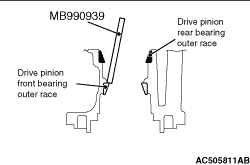
Use special remover bar (MB990939)
to remove the drive pinion front bearing outer
race.
|

|
Use special remover bar (MB990939)
to remove the drive pinion rear bearing outer race.
|

