
|
1.Make mating marks on the
radiator hose and the hose clamp. Disconnect the radiator
hose.
2.Disconnect the radiator hose.
|

|
Using special tool oil pressure
switch socket wrench (MB992118), removal the engine oil
pressure switch.
|

|
When loosening the nuts at both
ends of fuel injection pipe, hold the delivery holder
(for fuel injection pump side) and the fuel injection nozzle
(for fuel injection nozzle side)
with a wrench and loosen the nuts.
|

|
1.
| caution |
Never turn the crankshaft
anti-clockwise.
|
Turn the crankshaft clockwise, align the mating
marks on the camshaft sprocket with the
brilliant white mark ring plates on the timing chain to set
No. 1 cylinder to TDC (Top Dead Centre)
of its compression stroke.
|

|
2.
| caution |
- Do not lock the camshaft using the
timing chain.
- The camshaft sprocket bolt is left
threaded, so the arrow indicating its
tightening direction
is marked on the bolt head. To loosen
this bolt, turn the bolt to the opposite
direction of
the arrow.
- The timing chain must be attached to the
camshaft sprocket.
|
Hold the hexagonal part of the camshaft with an open
end wrench, loosen the camshaft sprocket
bolt, and then remove the camshaft sprocket with the timing
chain still attached.
3.Tie up the timing chain
and the camshaft sprocket with a cord to prevent the mating
mark misalignment.
|

|
1.Loosen the cylinder head
bolts in the shown sequence progressively, and then remove
the
cylinder head bolts.
2.Lift the cylinder head
assembly and cylinder head gasket straight without removing
the timing chain from the camshaft sprocket.
|
|
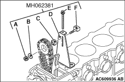
3.After the cylinder head
assembly and cylinder head gasket has been removed, use
special
tool camshaft sprocket holder kit (MH062381) to hold the
camshaft sprocket to prevent the timing
chain from sliding off.
- A: Nut
- B: Washer
- C: Spacer
- D: Adjust plate
- E: Bolt
- F: Nut
|

|
1.
| caution |
The thickness of the original
cylinder head gasket is selected according
to the protrusion amount of the piston.
Therefore, if the cylinder block, piston,
connecting
rod or crankshaft is replaced, the protrusion
amount may be changed. Always select a correct
gasket by measuring the protrusion amount.
(Refer to GROUP 11F -
Rocker Cover and Cylinder
Head Assembly  ). ).
|
To replace the cylinder head gasket only, select a
gasket of correct specification according
to the table below.
|
|
Notch specification
(fitted thickness
mm)
|
Part
number
|
A (1.35 ±
0.03 mm)
|
ME200751
|
B (1.40 ±
0.03 mm)
|
ME200752
|
C (1.45 ±
0.03 mm)
|
ME200753
|
D (1.50 ±
0.03 mm)
|
ME200754
|
|
2.
| caution |
Do not allow foreign material
to enter the engine coolant or oil passages
and the cylinder.
|
Clean the cylinder head assembly, the timing gear
case assembly, and the crankcase assembly
mating surfaces with a scraper or a wire brush.
|

|
3.
| caution |
After the engine oil pan is
installed, wait for at least one hour, and
then start the engine.
|
Apply the specified sealant to the upper side of the
mating surface between the timing
gear case and the crankcase assembly.
Specified
sealant: MITSUBISHI GENUINE PART MD970389 or
equivalent
4.
| caution |
When installing the cylinder
head gasket, be careful not to disturb the
sealant.
|
Immediately after applying the sealant, use the
cylinder head gasket to install the cylinder
head assembly to the crankcase.
|

|
5.
| caution |
The cylinder head bolts can be
reused up to 3 times. Therefore, the cylinder
head bolts with 3 punch marks already applied
must be replaced with new cylinder head bolts.
|
Apply punch marks to the bolt heads of the cylinder
head bolts.
|

|
6.Install the cylinder head
bolt washer to the cylinder head bolt so that the washer
chamfered
side faces as shown.
7.Apply a small amount of
engine oil to the cylinder head bolt thread and the
washer.
|


|
8.Tighten the cylinder head
bolts according to the following procedure (angle-tightening
procedure).
(1)
Tighten the bolts to 98 N·m in the order
shown.
Bolt size: Nominal diameter ×
length mm
- <Except 3, 6, 11, 14 >: 12 ×
105
- <
3, 6, 11, 14 >: 12 ×
125
(2)
Loosen the bolts fully in the reverse sequence to that
shown.
(3)
Tighten the bolts to 49 N·m in the order shown.
(4)
|
|
| caution |
- The bolt is not tightening
sufficiently if the
tightening angle is less
than a 90 degree
angle.
- If the tightening angle
exceeds the standard
specification, remove the
bolt and
start over from step
2.
|
|
Apply a paint mark to the heads of the cylinder head
bolts and cylinder head, then tighten
90 degree angle as shown.
(5)
Tighten in a 90 degree angle as shown in the instructions of
the figure, then check
to see that the paint mark on the head of the cylinder head
bolts and the paint mark on the
cylinder head is on a linear line.
(6)
|
|
| caution |
Whenever the
cylinder head bolts, are loosened
after the cylinder head
is installed, always apply the
sealant again.
|
|
Apply a small amount of engine oil to the thread and
the flange of bolts A, and tighten
them to A to 23 N·m.
|
|
|
1.Install the camshaft
sprocket to the camshafts with the timing chain
attached.
|
|
2.Hold the hexagonal part of
the camshaft with an open end wrench in the same manner as
removal.
3.Apply a small amount of engine oil to
the camshaft sprocket bolt thread and the flange,
and then tighten to the specified
torque.
Tightening torque: 88
N·m
|

|
Place the timing chain tensioner
gasket with its silicone print facing toward the timing
chain tensioner side.
|

|
1.Raise the cam, and then
push in the plunger, and lock the plunger using a
hook.
2.
| caution |
To install the timing chain
tensioner, always push in the plunger. If
you fail to do this, the timing chain will be
excessively tensioned, causing damage.
|
Install the timing chain tensioner to the cylinder
head.
3.
| caution |
If the crankshaft is turned
anti-clockwise after the timing chain tensioner
is installed, the plunger will be excessively
tensioned, causing the plunger to go beyond the
cam inside the timing chain tensioner.
|
Turn the crankshaft clockwise.
| note |
If the crankshaft is turned
clockwise after the timing chain tensioner is
installed, the plunger
is automatically unhooked. Then its internal
ratchet mechanism adjusts the timing chain
tension.
|
|
|
When tightening the nuts at both
ends of fuel injection pipe, hold the delivery holder
(for fuel injection pump side) and the fuel injection nozzle
(for fuel injection nozzle side)
with a wrench in the same manner as removal, and tighten the
nuts to the specified torque.
Tightening
torque: 23 N·m
|

|
1.
| caution |
Be careful not to block the
oil passage with sealant.
|
When reusing the sensor, apply the specified sealant
to the threads.
Specified sealant: 3M ATD Part
No. 8660 or equivalent
|
|
2.Tighten the engine oil
pressure switch together with the oil filter bracket to the
specified
torque, using special tool Oil pressure switch socket wrench
(MB992118).
Tightening torque: 19 ±
3 N·m
|
|
|
Insert the O-ring to pipe, and coat
the outer circumference of the O-ring with water.
|

|
1.Insert the radiator hose
as far as the projection of the thermostat case or water
outlet
pipe.
2.Align the mating marks on the radiator
hose and hose clamp, and then connect the radiator
hose.
|

