REMOVAL AND INSTALLATION


Pre-removal Operation
  • Battery and Battery Tray Removal (Refer to GROUP 54A - Battery ).
  • Under Skid Plate and Engine Room Under Cover (Front) Removal (Refer to GROUP 51 - Under Cover ).
  • Engine Coolant Draining (Refer to GROUP 14 - On-vehicle Service, Engine Coolant Replacement ).
  • Engine Oil Draining <4M4> (Refer to GROUP 12 - On-vehicle Service, Engine Oil Replacement ).
  • Air Cleaner Assembly and Air Intake Duct Removal <4M4> (Refer to GROUP 15 - Air Cleaner ).
  • Radiator Shroud Cover (Upper) Removal (Refer to GROUP 14 - Radiator ).
  • A/C Compressor Drive Belt, Alternator Drive Belt and Crankshaft Pulley Removal (Refer to ).
  • Cooling Fan and Cooling Fan Clutch Assembly Removal <4M4> (Refer to GROUP 14 - Radiator Fan ).
  • Alternator Assembly Removal <4M4> (Refer to GROUP 16 - Alternator assembly ).
  • Vacuum Pump Removal (Refer to ).
  • Water Pump Removal <4M4> (Refer to GROUP 14 - Water Pump ).
  • Cylinder Head and Cylinder Head Gasket Removal (Refer to ).
  • Engine Oil Pan Removal (Refer to ).

Post-installation Operation
  • Engine Oil Pan Installation (Refer to ).
  • Cylinder Head and Cylinder Head Gasket Installation (Refer to ).
  • Water Pump Installation <4M4> (Refer to GROUP 14 - Water Pump ).
  • Vacuum Pump Installation (Refer to ).
  • Alternator Assembly Installation <4M4> (Refer to GROUP 16 - Alternator assembly ).
  • Cooling Fan and Cooling Fan Clutch Assembly Installation <4M4> (Refer to GROUP 14 - Radiator Fan ).
  • A/C Compressor Drive Belt, Alternator Drive Belt and Crankshaft Pulley Installation (Refer to ).
  • Radiator Shroud Cover (Upper) Installation (Refer to GROUP 14 - Radiator ).
  • Air Cleaner Assembly and Air Intake Duct Installation <4M4> (Refer to GROUP 15 - Air Cleaner ).
  • Engine Oil Refilling <4M4> (Refer to GROUP 12 - On-vehicle Service, Engine Oil Replacement ).
  • Engine Coolant Refilling (Refer to GROUP 14, On-vehicle Service - Engine Coolant Replacement ).
  • Battery and Battery Tray Installation (Refer to GROUP 54A - Battery ).
  • Alternator Drive Belt Tension Check and Adjustment (Refer to ).
  • A/C compressor Drive Belt Tension Check and Adjustment (Refer to ).
  • Fuel line Air-bleeding (Refer to GROUP 13C - On-vehicle Service, Evacuation of Air From Fuel Line ).
  • Under Skid Plate and Engine Room Under Cover (Front) Installation (Refer to GROUP 51 - Under Cover ).


Removal steps
<<A>>

·
Power steering oil pump assembly
<<B>>

·
A/C compressor and A/C compressor bracket


1.
Harness bracket

>>B<<
2.
Timing gear case assembly


3.
Gasket


4.
Timing gear case stiffener

>>A<<
5.
Idler washer

>>A<<
6.
Camshaft sprocket
<<C>>
>>A<<
7.
Timing chain


8.
Tension lever assembly


9.
Tension lever shaft


10.
Engine oil jet


11.
Timing chain guide

REMOVAL SERVICE POINTS


<<A>> POWER STEERING OIL PUMP ASSEMBLY REMOVAL


1.With the hose installed, remove the power steering oil pump assembly from the engine assembly. (Refer to GROUP 37 - Power Steering Oil Pump Assembly ).
2.After removing the power steering oil pump assembly, secure it with a cord in the location where the removal and installation of the timing chain cannot be hindered.

<<B>> A/C COMPRESSOR AND A/C COMPRESSOR BRACKET REMOVAL


1.With the hose installed, remove the A/C compressor assembly from the engine assembly (Refer to GROUP 55 - Compressor Assembly ).
2.After removing the A/C compressor assembly, secure it with a cord in the location where the removal and installation of the timing chain cannot be hindered.
3.Remove the A/C compressor bracket from engine assembly (Refer to GROUP 55 - Compressor Assembly ).

<<C>> TIMING CHAIN REMOVAL


Remove special tool camshaft sprocket holder kit (MH062381) that is installed when removing the cylinder head assembly and cylinder head gasket. Then, remove the timing chain.

INSTALLATION SERVICE POINTS


>>A<< TIMING CHAIN/CAMSHAFT SPROCKET/IDLER WASHER INSTALLATION


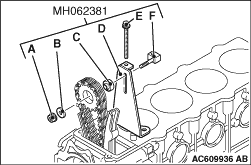
1.Using camshaft sprocket holder kit (MH062381), support the camshaft sprocket.

  • A: Nut
  • B: Washer
  • C: Spacer
  • D: Adjust plate
  • E: Bolt
  • F: Nut

2.Check that the mating mark “1” on the idler gear and sprocket assembly is in alignment with that on the crankshaft gear.

3.
caution Note that the timing chain has one mark plate for the idler gear and sprocket assembly side, and two mark plates for camshaft sprocket.
Align the mating mark on the idler gear and sprocket assembly with the brilliant white mark ring plate on the timing chain.

4.Align the mark ring plates with the camshaft sprocket mating marks.
5.Tie up the timing chain and the camshaft sprocket with a cord to prevent the mating mark misalignment.

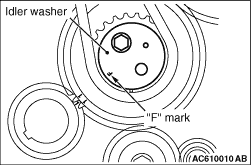
6.Install the idler washer. The idler washer front mark "F" must face toward the front of the engine.

>>B<< TIMING GEAR CASE ASSEMBLY INSTALLATION


1.Clean the timing gear case and the plate mating surfaces with a scraper or a wire brush.

2.
caution
  • After applying the sealant, install the timing gear case within 15 minutes.
  • When installing the timing gear case, be careful not to disturb the sealant.
  • Whenever the timing gear case mounting bolts are loosened or tightened again after the timing gear case installation, always apply the sealant again.
  • After the timing gear case is installed, wait for at least one hour, and then start the engine.
Apply a continuous bead of the specified sealant to the timing gear case mating surface as shown.
Specified sealant: MITSUBISHI GENUINE PART MD970389 or equivalent

3.Install the mounting nuts and bolts to the timing gear case at the shown positions.
Name
Symbol
Size (Nominal diameter × length mm)
Flange bole
A
6 × 16
B
8 × 50
C*
8 × 60
D
8 × 75
E
8 × 80
F
8 × 85
G
8 × 90
H
10 × 35
Cap nut
I
-
note *: Vehicle without A/C.