Pre-removal
Operation
- Battery and Battery Tray Removal (Refer to GROUP 54A
- Battery
 ). ).
- Under Skid Plate and Engine Room Under Cover (Front)
Removal (Refer to GROUP 51 - Under
Cover ).
- Engine Coolant Draining (Refer to GROUP 14 -
On-vehicle Service, Engine
Coolant Replacement ).
- Engine Oil Draining <4M4> (Refer to
GROUP 12 - On-vehicle
Service, Engine Oil Replacement ).
- Engine Cover Removal (Refer to ).
- Air Cleaner Assembly and Air Intake Duct Removal
<4M4> (Refer
to GROUP 15 - Air Cleaner ).
- Radiator Shroud Cover (Upper) Removal (Refer to
GROUP 14 - Radiator ).
- Cooling Fan and Cooling Fan Clutch Assembly Removal
<4M4> (Refer
to GROUP 14 - Cooling Fan ).
- A/C Compressor Drive Belt, Alternator Drive
Belt and Crankshaft Pulley
Removal (Refer to ).
- EGR Cooler Assembly and EGR Cooler Bracket Removal
(Refer to GROUP 17 - Emission
Control, EGR Valve and EGR Cooler ).
- Turbocharger Assembly and Exhaust Manifold Removal
(Refer to GROUP 15 - Exhaust
Manifold and Turbocharger Assembly ).
- Thermostat Removal <4M4> (Refer to GROUP
14 - Thermostat ).
- Vacuum Pipe Assembly, By-pass Pipe, Heater Return
Pipe and Thermostat Case Removal <4M4>
(Refer
to GROUP 14 - Water Hose and Water Pipe ).
- Throttle Body Assembly Removal (Refer to GROUP 13D
- Throttle Body Assembly ).
- Air Inlet Pipe and Inlet Manifold Assembly Removal
<4M41> (Refer
to GROUP 15 - Inlet Manifold ).
- Fuel Injector Assembly and Common Rail Assembly
Removal (Refer to GROUP 13D - Fuel
Injector and Common Rail ).
- Vacuum Pump Removal (Refer to ).
- Camshaft Assembly and Rocker Arm Removal (Refer to
).
- Cylinder Head and Cylinder Head Gasket Removal
(Refer to ).
- Engine Oil Pan Removal (Refer to ).
- Camshaft Position Sensor and Crank Angle Sensor
Removal (Refer to GROUP 13D - Camshaft
Position Sensor and Crank Angle Sensor ).
- Water Pump Removal <4M4> (Refer to GROUP
14 - Water Pump )
|
Post-installation
Operation
- Water Pump Installation <4M4> (Refer to
GROUP 14 - Water
Pump )
- Camshaft Position Sensor and Crank Angle Sensor
Installation (Refer to GROUP 13D - Camshaft
Position Sensor and Crank Angle Sensor ).
- Engine Oil Pan Installation (Refer to ).
- Cylinder Head and Cylinder Head Gasket Installation
(Refer to ).
- Camshaft Assembly and Rocker Arm Installation (Refer
to ).
- Vacuum Pump Installation (Refer to ).
- Fuel Injector Assembly and Common Rail Assembly
Installation (Refer to GROUP 13D - Fuel
Injector and Common Rail ).
- Air Inlet Pipe and Inlet Manifold Assembly
Installation <4M41> (Refer
to GROUP 15 - Inlet Manifold ).
- Throttle Body Assembly Installation (Refer to GROUP
13D - Throttle Body
Assembly ).
- Vacuum Pipe Assembly, By-pass Pipe, Heater Return
Pipe and Thermostat Case Installation
<4M4> (Refer
to GROUP 14 - Water Hose and Water Pipe ).
- Thermostat Installation <4M4> (Refer to
GROUP 14 - Thermostat ).
- Turbocharger Assembly and Exhaust Manifold
Installation (Refer to GROUP 15 - Exhaust
Manifold and Turbocharger Assembly ).
- EGR Cooler Assembly and EGR Cooler Bracket
Installation (Refer to GROUP 17 - Emission
Control, EGR Valve and EGR Cooler ).
- A/C Compressor Drive Belt, Alternator Drive
Belt and Crankshaft Pulley
Installation (Refer to ).
- Cooling Fan and Cooling Fan Clutch Assembly
Installation <4M4> (Refer
to GROUP 14 - Cooling Fan ).
- Radiator Shroud Cover (Upper) Installation (Refer to
GROUP 14 - Radiator ).
- Air Cleaner Assembly and Air Intake Duct
Installation <4M4> (Refer
to GROUP 15 - Air Cleaner ).
- Engine Cover Installation (Refer to ).
- Engine Oil Refilling <4M4> (Refer to
GROUP 12 - On-vehicle
Service, Engine Oil Replacement ).
- Engine Coolant Refilling (Refer to GROUP 14,
On-vehicle Service - Engine
Coolant Replacement ).
- Drive Belt Tension Check and Adjustment (Refer to ).
- Battery and Battery Tray Installation (Refer to
GROUP 54A - Battery ).
- Fuel line Air-bleeding (Refer to GROUP 13D -
On-vehicle Service, Evacuation
of Air From Fuel Line ).
- Under Skid Plate and Engine Room Under Cover (Front)
Installation (Refer to GROUP
51 - Under Cover ).
|
|
|
1.With the hose installed,
remove the power steering oil pump assembly from the engine
assembly. (Refer to GROUP 37 - Power Steering Oil Pump
Assembly ).
|
|
|
2.After removing the power
steering oil pump assembly, secure it with a cord in the
location where the removal and installation of the engine
assembly cannot be hindered.
|
|
|
Remove special tool camshaft
sprocket holder kit (MH063490) that is installed when
removing
the cylinder head assembly and cylinder head gasket. Then,
remove the timing chain.
|

|
1.Using special tool
camshaft sprocket holder kit (MH063490), support the
camshaft sprocket.
- A: Nut
- B: Washer
- C: Spacer
- D: Adjust plate
- E: Bolt
- F: Bolt
- G: Nut
|

|
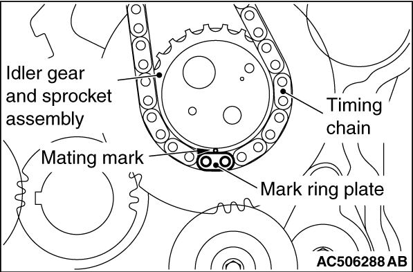
2.Check that the mating mark
“1” on the idler gear and sprocket assembly
is in alignment with that on the crankshaft gear.
|
|
3.
| caution |
Note that the timing chain has
one mark plate for the idler gear and sprocket
assembly side, and two mark plates for each
camshaft sprocket.
|
Align the mating mark on the idler gear and sprocket
assembly with the yellow mark ring
plate on the timing chain.
|

|
4.Align the mark ring plates
with the camshaft sprocket mating marks.
5.Tie up
the timing chain and the camshaft sprocket with a cord to
prevent the mating
mark misalignment.
|

|
6.Install the idler washer,
the spring pin and the oil jet. The idler washer front mark
"F" must face toward the front of the engine.
|

|
Install the idler A washer and the
chain bracket. The idler A washer front mark "F" must
face toward the front of the engine.
|
|
|
1.Clean the timing gear case
and the plate mating surfaces with a scraper or a wire
brush.
|

|
2.
| caution |
- After applying the sealant, install the
timing gear case within
15 minutes.
- When installing the timing gear case, be
careful not to disturb the
sealant.
- Whenever the timing gear case mounting
bolts are loosened or tightened again
after
the timing gear case installation,
always apply the sealant again.
- After the timing gear case is installed,
wait for at least one hour, and then
start
the engine.
|
Apply a continuous bead of the specified sealant to
the timing gear case mating surface
as shown.
Specified sealant: MITSUBISHI GENUINE
PART MD970389 or equivalent
|

|
3.Install the mounting nuts
and bolts to the timing gear case at the shown
positions.
|
|
Name
|
Symbol
|
Size (Nominal
diameter × length
mm)
|
Flange bole
|
A
|
8 × 75
|
B
|
8 × 85
|
C
|
8 × 90
|
D
|
8 × 55
|
E
|
8 × 60
|
F
|
10 × 60
|
Cap nut
|
G
|
-
|
|
|
