


|
- Install the special tool Valve spring compressor
adapter plate
(MD998784) on the cylinder heads shown in the
illustration.
- Install the special tool Valve spring compressor
(MD998772) on the special tools Valve
spring compressor adapter plate (MD998784).
- Press down the upper retainer and remove the valve
cotters.
- Using the special tool Valve spring compressor
(MD999597), compress the valve spring to
remove the valve cotters.
|
|
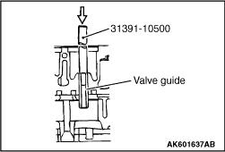
Remove the valve guide, using the
special tool Valve guide remover (31391-10500).
|

|
- The valve seat is expansion fitted.Reduce the seat
thickness by removing as much material
as necessary from inside the seat, and remove the
seat at normal
temperature.
|

|
- Warm the cylinder head to increase the clearance
between it and the combustion jet.
- Insert a round rod in the glow plug mounting hole in
the cylinder head. Tapping
on the rod with a hammer, remove the combustion jet
from the glow plug mounting hole together
with the tablet.
| caution |
Being made of ceramic,
the combustion jet is susceptible to
a shock. Do not hit it too hard, or it
maybe damaged.
|
|

|
1.Drive in the sealing caps
through to the specified depth. By way of precaution, apply
sealant to the press-fitting holes provided in the cylinder
head before driving the sealing
caps through in the holes.
|

|
Drive in each water director to the
specified depth, with its notch A set in the direction
shown in the illustration.
|

|
- Install the combustion jets in such a way that the
surface A may be brought into close
contact with the combustion chamber of the cylinder
head.
- Install the tablets to the combustion jets. then,
press-fit them into the cylinder
head in such a way that the surface B may be brought
into close contact with the combustion
jet.
| caution |
When it becomes
necessary to replace any combustion jet,
replace
the mated tablet at the same
time.
|
|

|
1.Measure the valve seat
mounting hole diameters B and C in the cylinder head. If a
measured
value is out of the standard value, select an oversize valve
seat from the following table.
Standard
value
Inlet (B): Φ
43.000 -
43.025 mm
Exhaust (C): Φ
37.000 -
37.025 mm
Correct the dimensions B, C, D
and E of valve seat mounting holes in the cylinder head
to those matching the outside diameters and thicknesses of
the selected oversize valve seats.
|
|
Oversize valve
seat
|
0.30 mm
|
0.60 mm
|
Inlet
|
I.D. (B)
|
Φ
43.300 -
43.325
|
Φ
43.600 -
43.625
|
Depth (D)
|
8.2 ±
0.1
|
8.5 ±
0.1
|
Exhaust
|
I.D. (C)
|
Φ
37.300 -
37.325
|
Φ
37.600 -
37.625
|
Depth (E)
|
8.3 ±
0.1
|
8.6 ±
0.1
|
|
|

|
2.Immerse the valve seats in
liquid nitrogen and cool enough.
3.Using the
special tool, install the valve seats in the mounting holes
till they bottom
the cylinder head properly.
4.After the valve
seats are installed, lap them and check the valve for proper
seating.
- Calking tool body (31391-13100)
- Calking inlet (MH062687)
- Calking exhaust (MH062688)
|

|
1.Measure the bore diameters
in the cylinder head for the valve guides. If measured value
is out of the standard value, select an oversize valve guide
from the following
table.
Standard
value
Bore diameter (A):13.000
-
13.018 mm
2.Correct the bore A to the inner
diameter matching the outside diameter of the selected
oversize valve guides.
|
|
Oversize valve
guide
|
0.05 mm
|
0.25 mm
|
0.50 mm
|
A: Valve guide
mounting hole diameter in cylinder
head
|
Φ
13.050 -
13.068
|
Φ
13.250 -
13.268
|
Φ
13.500 -
13.518
|
|
|

|
3.After installing the lower
retainers to the cylinder head, drive in the valve guides
all
the way till they certainly contact the lower retainers
positively.
| caution |
To install the valve guides to
the specified depth, be sure to
use the special tool Valve guide installer
(MH062686).
|
4.The exhaust valve guide is longer than the
intake valve guide. Be careful not to confuse
the valve guides.
|

|
1.Apply a thin coat of
engine oil to the lip A of the valve stem seal. Press in the
valve
stem seal by hand as deep as its bottom B contacts the top
surface of the valve guide.
2.Slowly press the
valve stem seal vertically till the special tool Valve stem
seal
installer (MH062671) contacts the lower retainer installed
in the cylinder head.
|

|
1.Install the special tools
Valve spring compressor adapter plate (MD998784) on the
cylinder
head as shown in the illustration.
|
|
2.Install the special tool
Valve spring compressor (MD998772) on the special tools
Valve
spring compressor adapter plate (MD998784).
|
|
3.Press down the upper
retainer and install the valve cotters.
|
|
4.Using the special tool
Valve spring compressor (MD999597), compress the valve
spring to
remove the valve cotters.
|

|
1.Install the valve spring
with the painted end A facing upward.
|

