
|
Use special tool Cylinder head bolt
wrench (MD998051) to loosen the cylinder head bolt.
|

|
1.Using special tool Valve
spring compressor (MD998735), compress the
spring.
2.Remove the retainer locks.
|

|
1.
| caution |
- Valve stem seals for intake valves and
for exhaust valves
are different. Be sure to install the
correct ones.
- Valve stem seal identification
color
Intake:
Gray
Exhaust: Gray green
|
Install the valve spring seat.
|
|
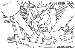
2.
| caution |
Always use the special tool to
install the valve stem seal. Improperly
installed
valve stem seals may leak oil.
|
Using special tool Valve stem seal installer
(MB991999), install a new stem seal to the
valve guide.
|

|
Install the valve spring end with
its identification color toward the spring
retainer.
|
|
Using special tool Valve spring
compressor (MD998735), compress the valve spring and insert
the retainer lock into position.
|

|
The cylinder head gasket
identification mark are stamped at the position shown in the
illustration.
|

|
| caution |
Attach the head bolt washer in
the direction shown in the figure.
|
1.Use special tool Cylinder head bolt wrench
(MD998051), tighten to specified torque
of 108 ±
5 N·m the bolts in two three stages in the illustrated
sequence.
2.Back off the bolts once and tighten
them to the specified torque in the same procedure
as shown in step 1.
|

