
|
1.Mark the cylinder number
on the side of the connecting rod big end for correct
reassembly.
2.Keep the removed connecting rods,
caps, and bearings in order according to the cylinder
number.
|

|
1.Not to damage the crank
pin, attach a special tool Bolt guide (MB992010), to the
connecting
rod bolt.
2.Remove the piston and connecting rod
assembly from the cylinder block.
|

|
1.2.The special tool
Piston pin setting tool (MD998780) consists of the elements
shown
in the illustration.
3.When removing the piston
pin, the special tool Guide D (MB991659) is also
used.
|

|
4.Insert Push rod, into the
piston from the front mark side, then attach Guide C, to the
push rod.
5.Place the piston and connecting rod
assembly on Base, with the front mark facing
up.
6.Use a press to remove the piston
pin.
| note |
Keep the disassembled pistons,
piston pins and connecting rods per
cylinder.
|
|
|
|
1.Insert the push rod into
the piston pin and install the guide "A."
|
|
|
2.Align the front mark of
the piston with that of the connecting rod. Align the piston
with the connecting rod.
|
|
|
3.Apply engine oil to the
outer circumference of the piston pin.
|

|
4.Insert the piston pin
guide "A" installed at Step 2 into the pin hole from the
front mark
of the piston.
5.Screw the guide "B" into "A"
until the clearance "L" reaches 2.25mm between "A" and
"B."
|

|
6.Place the piston and
connecting rod assembly onto Base, with the front marks
facing up.
7.Install the piston pin using a press.
If the required press force is less than the
standard value, replace the piston and piston pin assembly
or the connecting rod, or both.
Standard value:
7,350 - 17,150N
|


|
1.Fit the oil ring spacer
into the piston ring groove.
| note |
The side rails and spacer may
be installed in either direction.
|
2.
| caution |
Do not use any piston ring
expander when installing the
side rail.
|
Install the upper side rail.
To install the side
rail, first fit one end of the rail into the piston groove,
then press
the remaining portion into the position by finger. See
illustration.
Use of a ring expander to expand the side
rail end gap can break the side rail, unlike
other piston rings.
3.Install the lower side rail
in the same procedure as described in step 2.
| note |
Spacer and side rail sizes are
color-coded as follows:
|
|
Size
|
Identification
color
|
Standard
size
|
None
|
0.50 mm
oversize
|
Blue
|
1.00 mm
oversize
|
Yellow
|
|
To install a side rail, fit one end of
the rail into the groove, then press the rest of
the rail into position by hand as
shown.
|
4.Make sure that the side rails move smoothly
in either direction.
|

|
Using a piston ring expander, fit
the No.2 and then No.1 piston ring into position. The
ring end is provided with the identification
mark.
Identification mark
No.1
ring: T
No.2 ring: 2T or T2
|

|
| note |
The piston ring is stamped
with the following size mark.
|
|
Size
|
Identification
color
|
Standard
size
|
None
|
0.50 mm
oversize
|
50
|
1.00 mm
oversize
|
100
|
|
|
|
|
1.Liberally coat the
circumference of the piston, piston ring, and oil ring with
engine
oil.
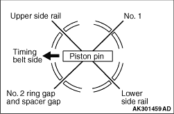
2.Arrange the piston ring and oil ring gaps
(side rail and spacer) as shown in the
illustration.
3.Rotate the crankshaft so that the
crank pin is on the center of the cylinder bore.
|

|
4.Not to damage the crank
pin, attach a special tool Bolt guide (MB992010), to the
connecting
rod bolt.
|

|
5.Insert the piston and
connecting rod assembly into the cylinder with the front
mark on
the piston crown pointing to the timing belt side.
|

|
6.Using a suitable piston
ring compressor tool, install the piston and connecting rod
assembly
into the cylinder block.
|

|
1.Verifying the mark made
during disassembly, install the bearing cap to the
connecting
rod. If the connecting rod is new with no index mark, make
sure that the bearing locking notches
are on the same side as shown.
|

|
2.Make sure that the
connecting rod big end side clearance meets the
specification.
Standard value: 0.10 -
0.25 mm
Limit: 0.3 mm
|
|
|
1.The connecting rod bolts
should be examined before reuse. If the bolt threads are
damaged, the bolt should be replaced.
Hand-thread the nut
to the full length of the bolt threads. If the nut does not
run down
smoothly, the bolt should be replaced.
|
|
|
2.Before installation of
each nut, apply engine oil to the threaded portion and
bearing
surface of the nut.
|
|
|
3.Loosely tighten each nut
to the bolt.
|
|
|
4.Then tighten the nuts
alternately to a torque of 27 N·m to install the cap
properly.
|

|
5.Make a paint mark on the
head of each nut.
6.Make a paint mark on the bolt
end at the position 90° (1/4 turn)
from the paint mark made on the nut in the direction of
tightening the nut.
7.
| caution |
- If the nut is turned
less than 90° (1/4 turn),
proper fastening performance may not be
achieved.
Be careful to tighten the nut exactly
90° (1/4 turn).
- If the nut is overtightened, loosen the
nut completely and then retighten it by
repeating the tightening procedure from
step 3.
|
Turn the nut further 90° (1/4 turn) and
make sure that the paint marks
on the nut and bolt are aligned.
|

