
|
Using the special tool Crankshaft
front oil seal installer (MH062469), remove the crankshaft
gear in the following manner.
| caution |
Apply engine oil to the sling
surface of plate and puller.
|
|

|
Using the special tool Balancer
shaft bearing puller (MH062490), remove the rear bearing
in the following manner.
| caution |
Apply engine oil to the sling
surface of plate and puller.
|
|

|
1.Set the tools as shown by
passing the remover, through the rear bearing while tilting
it as shown.
2.Pull the puller to bring the washer
into contact with the remover.
|

|
3.Secure the plate to the
crankcase using bolt.
| caution |
The securing position of the
plate is different between when
removing the left-hand and right-hand rear
bearing. Be sure to secure it in right
places.
|
|

|
4.Tighten the nut further to
remove the rear bearing.
|

|
Install the oil jet in such a way
that its pin is located at the illustrated
position.
|
|
|
When the bearing needs replacing,
select a proper bearing by the following procedure.
|
|
|
1.Measure the crankshaft
journal diameter and confirm its classification from the
following
table. In the case of a crankshaft supplied as a service
part, identification colors/marks of
its journals and painted at the positions shown in the
illustration.
|
|
|
2.The cylinder block bearing
bore diameter identification marks are stamped at the
position
shown in the illustration from front to rear beginning at
No. 1.
|
|
|
3.Select proper bearings
from the above table on the basis of the identification data
confirmed under Items (1) and (2).
|
|
|
4.Crankshaft bearing
(1)
Install the bearings having an oil groove to the cylinder
block.
|
|
| note |
The No. 3 bearing
integrated with thrust bearing has
no oil groove.
|
|
(2)
Install the bearings having no oil groove to the bearing
cap.
|

|
5.Install the thrust plates
and to crankshaft assembly at number 5 journal only. Install
all halves of the thrust plates with the oil groove oriented
outward.
| caution |
If any oversize thrust plates
are to be used, be sure to use an upper thrust
plate and lower thrust plate of the same size at
one side. However, using the same size upper
(or lower) thrust bearings on both sides is not
necessary.
|
|

|
| caution |
Before installing the lower
crankcase assembly, check the head of the main
cap bolt for punch marks. The number of punch
marks corresponds to the number of times the
bolt
has been tightened to the plastic area (Bolts
with two or less punch marks are reusable). If
there
are three, replace the main cap bolt.
|
|

|
1.Apply 2 mm thick bead of
specified sealant to the fitting surface of the upper
crankcase
assembly as shown.
Specified
sealant:
Mitsubishi Genuine Part No. MD970389 or
equivalent
| caution |
- Apply sealant
evenly, not broken or
oversupplied.
- Use care not to let the applied sealant
slip out of place during
installation.
|
|

|
2.Apply a thin cost of
engine oil to the threaded part and seating surface of each
main
cap bolt then tighten the bolts to a torque of 20 N·m
in the sequence of the numbers shown
(17 - 26).
3.After tightening, give the
bolts an additional 90° turn.
4.Then, give
the bolts another 90° turn to tighten them
completely.
5.Following the main cap bolts,
tighten the bolts to the specified torque 25 N·m
in the sequence of the numbers shown (1 - 16)
|

|
6.After installing the lower
crankcase assembly, check the following:
- Smooth rotation of crankshaft
assembly
- Make sure that the crankshaft turns
smoothly and the end play is correct. If the end
play
exceeds the limit, replace the crankshaft
bearings.
Standard value: 0.10 - 0.28
mm
Limit: 0.4 mm
|

|
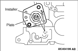
Using the special tool Balancer
shaft bearing installer (MH062717), install the rear bearing
in the following manner.
| caution |
Apply engine oil to the
sliding surfaces of the installer
and plate.
|
|

|
1.Fit the rear bearing onto
the installer from the non-chamfered side. At this time,
align
the oil hole with the alignment mark "-" on the
installer.
Align the oil hole of the left- hand bush with
the "L" line of the installer and the oil
hole of the right-hand bearing with the "R" line.
| caution |
Before installing the rear
bearing onto the installer apply
chassis grease to the inside surface of the
bearing so that the oil hole dose not slip out
of position.
|
|

|
2.Secure the plate to the
crankcase using bolt as shown.
| caution |
- Note that the securing position
of the plate is different between the
left-hand balance shaft bearing and the
right-hand bearing.
- Prior to securing the plate check that
the installer is correctly positioned
with
respect to the rear bearing.
|
|

|
3.Line up alignment mark
"-" on the installer and the alignment mark "-"
on the alignment mark plate.
|

|
4.Screw the nut onto the
installer up to its alignment mark "-" to predetermine
the press-fitting depth of the rear
bearing.
5.Strike on the installer until the nut
positively contacts the washer to press-fit
the rear bearing into the crankcase.
6.Check that
the oil hole of the rear bearing shaft bush is in alignment
with the oil
hole in the crankcase.
|

|
1.Before installing, heat
the crankshaft gear to approximately 100°C with a
piston heater or the like.
| caution |
Use care not to be
burned.
|
2.Align the notch in the crankshaft gear with
the key of the crankshaft then install
the crankshaft gear onto the crankshaft by tapping on the
end face lightly with a plastic hammer.
|

|
Apply a 2 mm thick bead of the
specified sealant to the lower crank case assembly and
upper crankcase assembly where indicated in the
illustration.
Specified
sealant:
Mitsubishi Genuine Part
No.MD970389 or equivalent
| caution |
- Apply the sealant evenly, not broken or
oversupplied.
- Use care not to let the applied sealant
slip out of place during
illustration.
- The bolt that holds the front plate is
also used to secure the timing gear case
is installed.
|
|

|
Press face "A" of the oil seal to
be on the same plane as the face "B" of the oil seal
case as shown in the drawing.
|

|
1.Apply a bead of FIPG to
the surface of the rear oil seal case as shown in the
drawing.
Specified
sealant:
Mitsubishi Genuine Part
No.MD970389 or equivalent
| note |
Be sure to install the case
quickly while the sealant is wet (within 15
minutes).
|
2.Install the oil seal into the cylinder
block after applying an appropriate amount
of engine oil to the entire circumference of its lip
portion.
3.Install the rear oil seal case by
tightening its bolts to 10 ± 2 N·m.
| note |
After installation, keep the
sealed area away from the oil for approximately
one hour.
|
|


