Code No.52: Valve Relay OFF Defective
| caution |
If there is any problem in the CAN bus lines, an
incorrect diagnosis code may be set. Diagnose the CAN bus lines before the
diagnosis codes (Refer to GROUP 54D, CAN bus-line diagnostic flow  ). ).
|


OPERATION
HBB is supplied with power for drive of each solenoid
valve from the fusible link No. 31 by turning ON the valve relay, and the
drive of each solenoid valve is controlled by ASTC-ECU.
DIAGNOSIS CODE SET CONDITIONS
Diagnosis code No. 52 is set if
ASTC-ECU judges that power for the solenoid valve is not supplied when
ASTC-ECU turns ON the valve relay.
PROBABLE CAUSES
The most likely causes for these diagnosis codes
to set are:
- Damaged wiring harness or connector
- Malfunction of the valve relay
- Malfunction of the ASTC-ECU
|
|
STEP 1. M.U.T.-III CAN bus diagnostics
|
|
|
| caution |
Before connecting or disconnecting the M.U.T.-III,
turn the ignition switch to the "LOCK" (OFF) position.
|
|
|
|
(1)Connect M.U.T.-III to the 16-pin diagnosis
connector.
|
|
|
(2)Turn the ignition switch to the "ON" position.
|
|
|
(3)Diagnose the CAN bus line.
|
|
|
(4)Turn the ignition switch to the "LOCK" (OFF)
position.
|
|
|
Q.
Is the check result normal?
|
|
|
 Go to Step 3. Go to Step 3.
|
|
|
|
|
|
 Repair the CAN bus line (Refer to
GROUP 54D, CAN bus line Diagnostic flow ). Then go to Step 2. Repair the CAN bus line (Refer to
GROUP 54D, CAN bus line Diagnostic flow ). Then go to Step 2.
|
|
|
|
|
|
STEP 2. Check whether the diagnosis code is reset.
|
|
|
| caution |
Before connecting or disconnecting the M.U.T.-III,
turn the ignition switch to the "LOCK" (OFF) position.
|
|
|
|
(1)Turn the ignition switch to the "ON" position.
|
|
|
(2)Erase the diagnosis code.
|
|
|
(3)Turn the ignition switch to the "LOCK" (OFF)
position.
|
|
|
(4)Turn the ignition switch to the "ON" position.
|
|
|
(5)Check if the diagnosis code is set.
|
|
|
(6)Turn the ignition switch to the "LOCK" (OFF)
position.
|
|
|
Go to Step 3.
|
|
|
|
|
|
The
procedure is complete.
|
|
|
|
|
|
STEP 3. Check the valve relay.
|
|
|
Refer to .
|
|
|
Q.
Is the check result normal?
|
|
|
Go to Step 4.
|
|
|
|
|
|
Replace the valve relay. Then go
to Step 9.
|
|
|
|
|
|
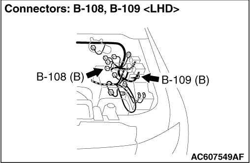
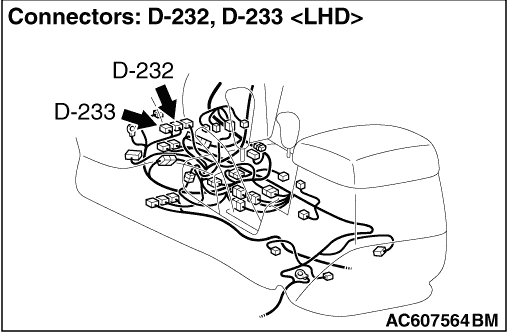
STEP 4. Check valve relay connector B-17X, Diode connector B-109,
ASTC-ECU connector D-232 and ASTC-ECU connector D-233 for loose, corroded
or damaged terminals, or terminals pushed back in the
connector.
|
|
|
Q.
Is the check result normal?
|
|
|
Go to Step 5.
|
|
|
|
|
|
Repair or replace the damaged
component(s). Then go to Step 9.
|
|
|
|
|
|
STEP 5. Check the harness wires between valve relay connector B-17X
terminal No.4 and earth.
|
|
|
Check for open circuit or short to power
supply.
|
|
|
Q.
Is the check result normal?
|
|
|
Go to Step 6.
|
|
|
|
|
|
Repair the wiring harness. Then
go to Step 9.
|
|
|
|
|
|
STEP 6. Check the harness wires between valve relay connector B-17X
terminal No.2 and ASTC-ECU connector D-232 terminal No.62.
|
|
|
| note |
When the wiring harness is checked for continuity,
connect the circuit tester as shown in the figure because a diode is
installed.
|
|
|
|
Check for open circuit or short to power
supply.
|
|
|
Q.
Is the check result normal?
|
|
|
Go to Step 7.
|
|
|
|
|
|
Repair the wiring harness. Then
go to Step 9.
|
|
|
|
|
|
STEP 7. Check the harness wires between valve relay connector B-17X
terminal No.2 and HBB connector B-108 terminal No.34.
|
|
|
Check for open circuit or short to
earth.
|
|
|
Q.
Is the check result normal?
|
|
|
Go to Step 8.
|
|
|
|
|
|
Repair the wiring harness. Then
go to Step 9.
|
|
|
|
|
|
STEP 8. Check whether the diagnosis code is reset.
|
|
|
Check again if the diagnosis code is
set.
|
|
|
(1)Turn the ignition switch to the "ON" position.
|
|
|
(2)Erase the diagnosis code.
|
|
|
(3)Turn the ignition switch to the "LOCK" (OFF)
position.
|
|
|
(4)Turn the ignition switch to the "ON" position.
|
|
|
(5)Check if the diagnosis code is reset.
|
|
|
(6)Turn the ignition switch to the "LOCK" (OFF)
position.
|
|
|
Replace the ASTC-ECU. Then go to
Step 9.
|
|
|
|
|
|
It can
be assumed that this malfunction is intermittent. Refer to GROUP 00, How to
Use Troubleshooting/Inspection Service Points - How to Cope
with Intermittent Malfunction .
|
|
|
|
|
|
STEP 9. Check whether the diagnosis code is reset.
|
|
|
(1)Turn the ignition switch to the "ON" position.
|
|
|
(2)Erase the diagnosis code.
|
|
|
(3)Turn the ignition switch to the "LOCK" (OFF)
position.
|
|
|
(4)Turn the ignition switch to the "ON" position.
|
|
|
(5)Check if the diagnosis code is set.
|
|
|
(6)Turn the ignition switch to the "LOCK" (OFF)
position.
|
|
|
Repeat the troubleshooting from
Step 1.
|
|
|
|
|
|
The
procedure is complete.
|
|
|
|