Pre-removal
Operation
- Power Steering Fluid Draining (Refer to
 ). ).
- Under Cover Removal (Refer to GROUP 51, Under Cover
).
- Front Differential and Propeller Shaft disconnection
(Refer to GROUP 25, Propeller
Shaft ).
- Wheel Speed Sensor Harness Bracket, Free Wheel
Actuator Connector and Hose disconnection
(Refer to GROUP 26, Differential Carrier and Free
Wheeling Clutch ).
- Differential Mount Bracket Front Mounting Bolts
removal (Refer to GROUP 26, Front
Differential Mount ).
|
Post-installation Operation
- Differential Mount Bracket Front Mounting Bolts
installation (Refer to GROUP 26,
Front Differential Mount ).
- Wheel Speed Sensor Harness Bracket, Free Wheel
Actuator Connector and Hose connection
(Refer to GROUP 26, Differential Carrier and Free
Wheeling Clutch ).
- Front Differential and Propeller Shaft Connection
(Refer to GROUP 25, Propeller
Shaft ).
- Under Cover Installation (Refer to GROUP 51, Under
Cover ).
- Fill Power Steering Fluid and bleed air (Refer to ).
- Check the Dust Cover for Cracks or Damage by Pushing
it with Finger.
- Check the Steering Angle (Refer to ).
|

|
1.Install the special tool
ball joint remover (MB991897 or MB992011) as shown in the
figure.
|

|
2.Turn the bolt and knob as
necessary to make the jaws of the special tool parallel,
tighten
the bolt by hand and confirm that the jaws are still
parallel.
| note |
When adjusting the jaws in
parallel, make sure the knob is in the position
shown in the
figure.
|
3.Tighten the bolt with a wrench to
disconnect the tie rod end.
|


|
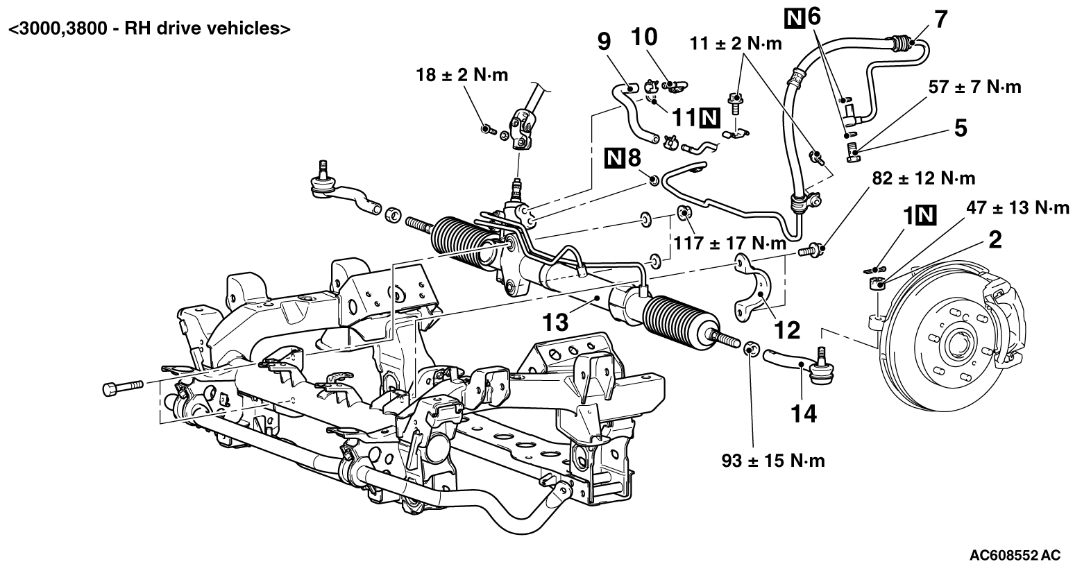
1.Align the mating marks on
the gear box, return tube assembly and pressure tube
assembly
when installing.
2.Install so that the mating
marks and upward.
|

|
3.Install so that the
markings are faced upward.
|

|
Screw the tie rod to the dimension
shown in the illustration and secure it temporarily
with the jam nut.
| note |
Tighten the locknut to the
specified torque after installing the gearbox
onto the body
and adjusting the toe-in.
|
Reference value A:
<Short wheel
base> 46mm
<Long
wheel base> 41mm
|