The Inside Rear
View Mirror can’t be Set to Night Mode


COMMENTS ON TROUBLE SYMPTOM
When the mirror switch is set to
"AUTO", the anti-glare function is activated automatically
TROUBLESHOOTING HINTS
- Malfunction of connector.
- Malfunction of the inside rear view mirror assembly.
|
|
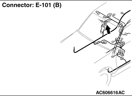
STEP 1. Connector check: E-101 inside rear view mirror assembly
connector
|
|
|
Q.
Is the check result normal?
|
|
|
 Go to Step 2. Go to Step 2.
|
|
|
|
|
|
 Repair
or replace the connector. Repair
or replace the connector.
|
|
|
|
|
|
STEP 2. Voltage measurement at E-101 inside rear view mirror assembly
connector.
|
|
|
(1)Disconnect inside rear view mirror assembly connector
E-101, and measure the voltage
at the wiring harness side.
|
|
|
(2)Turn the ignition switch to the "ON" position.
|
|
|
(3)Measure the voltage between terminal 1 and
earth.
OK: Approximately 12 volts (battery positive
voltage)
|
|
|
Q.
Is the check result normal?
|
|
|
Go to Step 4.
|
|
|
|
|
|
Go to Step 3.
|
|
|
|
|
|
STEP 3. Check the wiring harness E-101 between inside rear view mirror
assembly connector terminal No.1 and the ignition switch
(IG2).
|
|
|
| note |
Prior to the wiring harness inspection, check
intermediate connector D-130, junction block
connectors D-410 and D-403, and repair if necessary.
|
|
|
|
Q.
Is the check result normal?
|
|
|
The
trouble can be an intermittent malfunction (Refer to GROUP 00, How to Cope
with Intermittent Malfunction  ). ).
|
|
|
|
|
|
Repair
the wiring harness.
|
|
|
|
|
|
STEP 4. Resistance measurement E-101 inside rear view mirror assembly
connector.
|
|
|
(1)Disconnect the connector, and measure at the wiring
harness side.
|
|
|
(2)Measure the resistance value between terminal 2 and
earth.
OK: Continuity (Less than 2 Ω)
|
|
|
Q.
Is the check result normal?
|
|
|
Go to Step 6.
|
|
|
|
|
|
Go to Step 5.
|
|
|
|
|
|
STEP 5. Check the wiring harness between E-101 inside rear view mirror
assembly connector terminal No.2 and earth.
|
|
|
Q.
Is the check result normal?
|
|
|
The
trouble can be an intermittent malfunction (Refer to GROUP 00, How to Cope
with Intermittent Malfunction ).
|
|
|
|
|
|
Repair
the wiring harness.
|
|
|
|
|
|
STEP 6. Voltage measurement at E-101 inside rear view mirror assembly
connector.
|
|
|
(1)Disconnect inside rear view mirror assembly connector
E-101, and measure the voltage
at the harness side.
|
|
|
(2)Turn the ignition switch to the "ON" position.
|
|
|
(3)Shift the selector lever to the "R" range.
<A/T>
|
|
|
(4)Shift the lever to the "R" position.
<M/T>
|
|
|
(5)Measure the resistance value between terminal 3 and
earth.
OK: Approximately 12 volts (battery positive
voltage)
|
|
|
Q.
Is the check result normal?
|
|
|
Go to Step 17.
|
|
|
|
|
|
NO <A/T> : Go to Step 7. : Go to Step 7.
|
|
|
|
|
|
NO <M/T> : Go to Step 12.
|
|
|
|
|
|
STEP 7. Connector check: C-05 inhibitor switch connector
|
|
|
Q.
Is the check result normal?
|
|
|
Go to Step 8.
|
|
|
|
|
|
Repair
or replace the damaged component(s). Refer to GROUP 00, Harness Connector
Inspection .
|
|
|
|
|
|
STEP 8. Check the inhibitor switch.
|
|
|
Refer to GROUP 23A, Inhibitor Switch Continuity
Check .
|
|
|
Q.
Is the check result normal?
|
|
|
Go to Step 9.
|
|
|
|
|
|
Replace the inhibitor switch.
|
|
|
|
|
|
STEP 9. Check the ignition switch (IG1) circuit to the inhibitor
switch.
Measure the voltage at inhibitor switch connector C-05.
|
|
|
(1)Disconnect inhibitor switch connector C-05 and measure the
voltage available at
the wiring harness side of the connector.
|
|
|
(2)Turn the ignition switch to the "ON" position.
|
|
|
(3)Measure the resistance value between terminal 7 and
earth.
OK: Approximately 12 volts (battery positive
voltage)
|
|
|
Q.
Is the check result normal?
|
|
|
Go to Step 11.
|
|
|
|
|
|
Go to Step 10.
|
|
|
|
|
|
STEP 10. Check the wiring harness between C-05 inhibitor switch
connector
terminal No.7 and the ignition switch (IG1).
|
|
|
| note |
Prior to the wiring harness inspection, check
intermediate connectors D-225 and C-229,
junction block connectors D-401 and D-403, and repair if
necessary.
|
|
|
|
Q.
Is the check result normal?
|
|
|
No
action is necessary and testing is complete.
|
|
|
|
|
|
The
wiring harness may be damaged or the connector(s) may have loose, corroded
or damaged terminals, or terminals pushed back in the connector. Repair the
wiring harness as
necessary.
|
|
|
|
|
|
STEP 11. Check the wiring harness between E-101 inside rear view mirror
assembly connector terminal No.3 and C-05 inhibitor switch connector
terminal No.8.
|
|
|
| note |
Prior to the wiring harness inspection, check
intermediate connectors D-130, D-225 and
D-230, and repair if necessary.
|
|
|
|
Q.
Is the check result normal?
|
|
|
The
trouble can be an intermittent malfunction (Refer to GROUP 00, How to Cope
with Intermittent Malfunction ).
|
|
|
|
|
|
Repair
the wiring harness.
|
|
|
|
|
|
STEP 12. Connector check: C-17 back-up lamp switch
connector
|
|
|
Q.
Is the check result normal?
|
|
|
Go to Step 13.
|
|
|
|
|
|
Repair
or replace the damaged component(s). Refer to GROUP 00, Harness Connector
Inspection .
|
|
|
|
|
|
STEP 13. Check the back-up lamp switch.
|
|
|
Q.
Is the check result normal?
|
|
|
Go to Step 14.
|
|
|
|
|
|
Repair
the back-up lamp switch.
|
|
|
|
|
|
STEP 14. Check the ignition switch (IG1) circuit to the backup light
switch. Measure the voltage at back-up lamp switch connector
C-17.
|
|
|
(1)Disconnect inside rear view mirror assembly connector
E-101, and measure the voltage
at the harness side.
|
|
|
(2)Turn the ignition switch to the "ON" position.
|
|
|
(3)Measure the resistance value between terminal 2 and
earth.
OK: Approximately 12 volts (battery positive
voltage)
|
|
|
Q.
Is the check result normal?
|
|
|
Go to Step 16.
|
|
|
|
|
|
Go to Step 15.
|
|
|
|
|
|
STEP 15. Check the wiring harness between C-17 back-up lamp switch
connector terminal No.2 and the ignition switch (IG1).
|
|
|
| note |
Prior to the wiring harness inspection, check
intermediate connectors D-225 and D-229,
junction block connectors D-401and D-403, and repair if
necessary.
|
|
|
|
Q.
Is the check result normal?
|
|
|
No
action is necessary and testing is complete.
|
|
|
|
|
|
The
wiring harness may be damaged or the connector(s) may have loose, corroded
or damaged terminals, or terminals pushed back in the connector. Repair the
wiring harness as
necessary.
|
|
|
|
|
|
STEP 16. Check the wiring harness between E-101 inside rear view mirror
assembly connector terminal No.3 and C-17 back-up lamp switch connector
terminal No.1.
|
|
|
| note |
Prior to the wiring harness inspection, check
intermediate connectors D-130, D-225 and
D-230, and repair if necessary.
|
|
|
|
Q.
Is the check result normal?
|
|
|
The
trouble can be an intermittent malfunction (Refer to GROUP 00, How to Cope
with Intermittent Malfunction ).
|
|
|
|
|
|
Repair
the wiring harness.
|
|
|
|
|
|
STEP 17. Check the inside rear view mirror assembly.
|
|
|
Refer to .
|
|
|
Q.
Is the check result normal?
|
|
|
The
trouble can be an intermittent malfunction (Refer to GROUP 00, How to Cope
with Intermittent Malfunction ).
|
|
|
|
|
|
Repair
the inside rear view mirror assembly.
|
|
|
|