Code No.B1476: Power Supply Voltage (Ig1 (A) Voltage) Drops Abnormally.
(Fuse No.2 Circuit)
Code No.B1477: Power Supply Voltage (Ig1 (B)
Voltage) Drops Abnormally. (Fuse No.3 Circuit)


| caution |
If diagnosis code B1476 Fuse No.2 or B1477 Fuse No.3
is set in the SRS-ECU always diagnose the CAN bus lines.
|
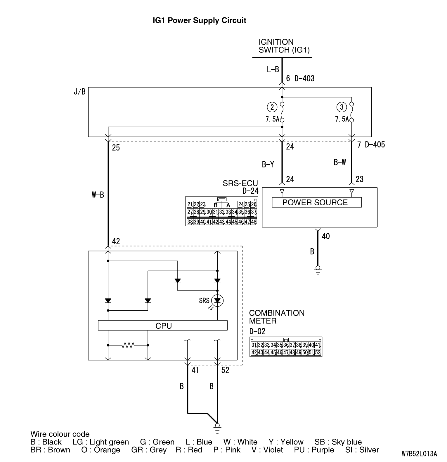
OPERATION
- The SRS-ECU is powered from the ignition switch (IG1).
- The SRS-ECU power is supplied from two circuits. Even if one circuit is
shut off, the air bag can inflate.
DIAGNOSIS CODE SET CONDITIONS
This diagnosis code is set if the
voltage between the IG1 terminals (fuse No.2 circuit or fuse No.3 circuit) and
earth is lower than a predetermined value for a continuous period of 5 seconds
or more.
PROBABLE CAUSES
- Damaged wiring harnesses or connectors
- Malfunction of the SRS-ECU
|
|
STEP 1. M.U.T.-III CAN bus diagnostics.
|
|
|
Use the M.U.T.-III to diagnose the CAN bus
lines.
|
|
|
Q.
Is the check result normal?
|
|
|
 Go to Step 2. Go to Step 2.
|
|
|
|
|
|
 Repair
the CAN bus line (Refer to GROUP 54D, Diagnosis Repair
the CAN bus line (Refer to GROUP 54D, Diagnosis  ). ).
|
|
|
|
|
|
STEP 2. Check whether the diagnosis code is reset.
|
|
|
Check again if the diagnosis code is
set.
|
|
|
(1)Erase the diagnosis code.
|
|
|
(2)Ignition: "LOCK" (OFF) position to "ON"
|
|
|
(3)On completion, check that the diagnosis code is not
reset.
|
|
|
Q.
Is the diagnosis code set?
|
|
|
Go to Step 3.
|
|
|
|
|
|
There
is an intermittent malfunction such as poor engaged connector(s) or open
circuit (Refer to GROUP 00, How to Cope with Intermittent Malfunction ).
|
|
|
|
|
|
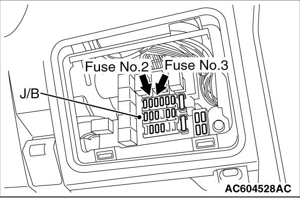
STEP 3. Check junction block fuse number 2 <B1476> or 3
<B1477>.
|
|
Q.
Is the fuse burned out?
Go to Step 6.
Go to Step
4.
|
|
|
STEP 4. Check the power supply circuit for open circuit. Voltage
measurement at SRS-ECU connector D-24.
|
|
|
(1)Disconnect the negative battery terminal.
|
|
|
(2)Disconnect SRS-ECU connector D-24.
|
|
|
(3)Connect the negative battery terminal.
|
|
|
(4)Turn the ignition switch to the "ON" position.
|
|
|
(5)
| caution |
Do not insert a test probe into the terminal from
its front side directly, as the connector contact pressure may be
weakened.
|
Measure the voltage between D-24 harness side connector terminal 24
<B1476> or 23 <B1477> and body
earth.
OK: 9 V or more.
|
|
|
Q.
Is the measured voltage within the specified range?
|
|
|
Go to Step 10.
|
|
|
|
|
|
Go to Step 5.
|
|
|
|
|
|
STEP 5. Wiring harness check between the SRS-ECU connector D-24 and the
ignition switch connector D-309.
|
|
|
| note |
Prior to the wiring harness inspection, check the
junction block connectors D-403 and D-405, and repair if
necessary.
- Open circuit check for the SRS-ECU power supply wire
|
|
|
|
Q.
Is the check result normal?
|
|
|
Go to Step 10.
|
|
|
|
|
|
Repair
or replace it.
|
|
|
|
|
|
STEP 6. Check a burned-out fuse.
|
|
|
(2)Turn the ignition switch to the "ON" position, wait for at
least one minute and then the ignition switch to the "LOCK" (OFF) position.
|
|
|
Q.
Is the fuse in good condition?
|
|
|
The
procedure is complete.
|
|
|
|
|
|
Go to Step 7.
|
|
|
|
|
|
STEP 7. Check the SRS-ECU power supply circuit for short circuit to
earth. Resistance measurement at the junction block connector
D-405.
|
|
|
(1)Disconnect junction block connector D-405, and measure at
the wiring harness side.
|
|
|
(2)
| caution |
Do not insert a test probe into the terminal from
its front side directly as the connector contact pressure may be
weakened.
|
Measure the resistance between terminal 24 <B1476> or 7
<B1477> and body earth.
OK: Open
circuit
|
|
|
Q.
Is the check result normal?
|
|
|
Go to Step 8.
|
|
|
|
|
|
Go to Step 9.
|
|
|
|
|
|
STEP 8. Check the SRS-ECU power supply circuit for short circuit to
earth. Resistance measurement at the junction block connector
D-405.
|
|
|
(1)Disconnect junction block connector D-405, and measure at
the wiring harness side.
|
|
|
(2)
| caution |
Do not insert a test probe into the terminal from
its front side directly as the connector contact pressure may be
weakened.
|
Measure the resistance between terminal 25 and body
earth.
OK: Open circuit
|
|
|
Q.
Is the check result normal?
|
|
|
Check
the other circuit, which flows through fuse No.2.
|
|
|
|
|
|
Repair
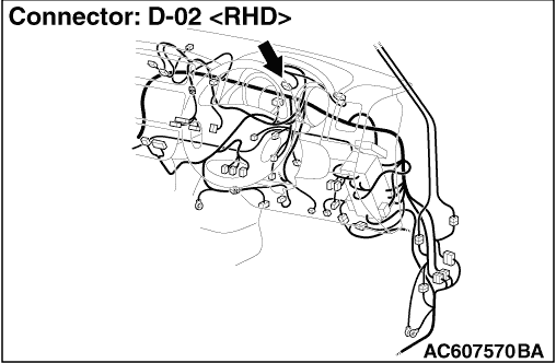
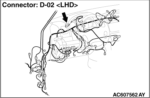
the harness wires between junction block connector D-405 (terminal No.25)
and combination meter connector D-02 (terminal No.42).
|
|
|
|
|
|
STEP 9. Check the power supply circuit for short circuit to earth.
Resistance measurement at the SRS-ECU connector D-24.
|
|
|
(1)Disconnect SRS-ECU connector D-24, and measure at the
wiring harness side.
|
|
|
(2)
| caution |
Do not insert a test probe into the terminal from
its front side directly as the connector contact pressure may be
weakened.
|
Measure the resistance between terminal 24 <B1476> or 23
<B1477> and body earth.
OK: Open
circuit
|
|
|
Q.
Is the check result normal?
|
|
|
Go to Step 10.
|
|
|
|
|
|
Repair
the wiring harness between SRS-ECU connector D-24 (terminal No.24 and 23)
and junction block connector D-405 (terminal No.24 and 7).
|
|
|
|
|
|
STEP 10. Check whether the diagnosis code is reset.
|
|
|
Q.
Is diagnosis code B1476 or B1477 set?
|
|
|
Replace the SRS-ECU (Refer to ).
|
|
|
|
|
|
An
intermittent malfunction is suspected (Refer to GROUP 00, How to Cope with
Intermittent Malfunction ).
|
|
|
|