Inspection Procedure 2: Speedometer does not Work (Other Meters
Work).


|
|
COMMENTS ON TROUBLE SYMPTOM
|
|
|
If only the speedometer does not operate, the
engine ECU system, the combination meter, the wiring harness or its
connector may be defective. Furthermore, incorrect level of fuel is shown
on the gauge, because the display unit cannot learn the fuel
gauge.
|
|
|
- Damaged harness wires and connectors
- Malfunction of vehicle speed sensor
- Malfunction of combination meter
|
|
|
STEP 1. Connector check: C-16 vehicle speed sensor
connector.
|
|
|
Q.
Is C-16 vehicle speed sensor connector in good condition?
|
|
|
 Go to Step 2. Go to Step 2.
|
|
|
|
|
|
 Repair
or replace the damage component(s). Repair
or replace the damage component(s).
|
|
|
|
|
|
STEP 2. Check the vehicle speed sensor.
|
|
|
Check the vehicle speed sensor (Refer to  ). ).
|
|
|
Q.
Is the check result normal?
|
|
|
Go to Step 3.
|
|
|
|
|
|
Replace the vehicle speed
sensor.
|
|
|
|
|
|
STEP 3. Resistance measurement at C-16 vehicle speed sensor
connector.
|
|
|
(1)Disconnect the connector, and measure at the wiring
harness side.
|
|
|
(2)Measure the resistance between C-16 vehicle speed sensor
connector terminal No.2 and body earth
OK: Continuity exists (2
Ω or less)
|
|
|
Q.
Is the check result normal?
|
|
|
Go to Step 5.
|
|
|
|
|
|
Go to Step 4.
|
|
|
|
|
|
STEP 4. Check the wiring harness between C-16 vehicle speed sensor
connector terminal No.2 and body earth.
|
|
|
- Check the earth wires for open circuit.
|
|
|
Q.
Is the check result normal?
|
|
|
The
trouble can be an intermittent malfunction (Refer to GROUP 00 - How
to Cope with Intermittent Malfunction ).
|
|
|
|
|
|
Repair
the wiring harness.
|
|
|
|
|
|
STEP 5. Voltage measurement at C-16 vehicle speed sensor
connector.
|
|
|
(1)Disconnect the connector, and measure at the wiring
harness side.
|
|
|
(2)Turn the ignition switch to the ON position.
|
|
|
(3)Measure the voltage between terminal 1 and body
earth
OK: System voltage
|
|
|
Q.
Is the check result normal?
|
|
|
Go to Step 7.
|
|
|
|
|
|
Go to Step 6.
|
|
|
|
|
|
STEP 6. Check the wiring harness between C-16 vehicle speed sensor
connector terminal No.1 and the ignition switch (IG1).
|
|
|
| note |
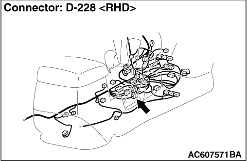
Prior to the wiring harness inspection, check
junction block connectors D-403, D-405 and intermediate connector D-228,
and repair if necessary.
|
|
|
|
- Check the power supply line to the ignition switch (IG1) for open
circuit.
|
|
|
Q.
Is the check result normal?
|
|
|
The
trouble can be an intermittent malfunction (Refer to GROUP 00 - How
to Cope with Intermittent Malfunction ).
|
|
|
|
|
|
Repair
the wiring harness.
|
|
|
|
|
|
STEP 7. Connector check: D-04 combination meter connector
|
|
|
Q.
Is the check result normal?
|
|
|
Go to Step 8.
|
|
|
|
|
|
Repair
the defective connector.
|
|
|
|
|
|
STEP 8. Check the wiring harness between D-04 combination meter
connector terminal No.15 and C-16 vehicle speed sensor connector terminal
No.3.
|
|
|
| note |
Prior to the wiring harness inspection, check
intermediate connector D-228, and repair if necessary.
|
|
|
|
- Check the input line for open circuit.
|
|
|
Q.
Is the check result normal?
|
|
|
Go to Step 9.
|
|
|
|
|
|
Repair
the wiring harness.
|
|
|
|
|
|
STEP 9. Retest the system.
|
|
|
Q.
Is the speedometer normal?
|
|
|
The
procedure is complete. (If no malfunctions are found in all steps, an
intermittent malfunction is suspected. Refer to GROUP 00 - How to
Cope with Intermittent Malfunction ).
|
|
|
|
|
|
Replace the combination meter
assembly.
|
|
|
|