Inspection Procedure 6: The Reversing Sensor OFF Indicator keeps
Flashing.


|
|
COMMENTS ON TROUBLE SYMPTOM
|
|
|
If either reversing sensor (corner sensor/back
sensor) does not detect the obstacle, the wiring harness, connectors,
corner sensor-ECU may be defective.
|
|
|
- Damaged harness wires and connectors
- Malfunction of reversing (corner sensor/back sensor)
- Malfunction of corner sensor-ECU
|
|
|
STEP 1. Connector check: D-16 corner sensor-ECU.
|
|
|
Q.
Is the check result normal?
|
|
|
 Go to Step 2. Go to Step 2.
|
|
|
|
|
|
 Repair
the defective connector. Repair
the defective connector.
|
|
|
|
|
|
STEP 2. Voltage measurement at D-16 corner sensor-ECU connector in
order to power supply circuit to corner sensor-ECU (IG2 power
supply)
|
|
|
(1)Disconnect D-16 corner sensor-ECU connector, and measure
at the wiring harness side.
|
|
|
(2)Turn the ignition switch to "ON" position.
|
|
|
(3)Measure the voltage between terminal 11 and
earth.
OK: System voltage
|
|
|
Q.
Is the check result normal?
|
|
|
Go to Step 4.
|
|
|
|
|
|
Go to Step 3.
|
|
|
|
|
|
STEP 3. Check the wiring harness between D-16 corner sensor-ECU
connector terminal No. 11 and ignition switch (IG2).
|
|
|
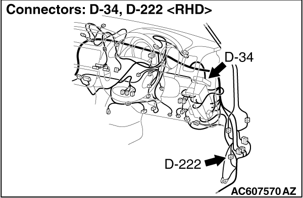
| note |
Before the wiring harness inspection, inspect
junction block connector D-403 and D-405,and joint connector D-34, and
repair if necessary.
|
|
|
|
Q.
Is the check result normal?
|
|
|
Retest
the system.
|
|
|
|
|
|
Repair
the wiring harness.
|
|
|
|
|
|
STEP 4. Confirm which reversing sensor (corner sensor/back sensor) does
not detect the obstacle.
|
|
|
Q.
Which reversing sensor (corner sensor/back sensor) does not detect the
obstacle?
|
|
|
Corner sensor (rear: RH) : Go to Step 5. : Go to Step 5.
|
|
|
|
|
|
Corner sensor (rear: LH) : Go to Step 8.
|
|
|
|
|
|
Back sensor (RH) : Go to Step 11.
|
|
|
|
|
|
Back sensor (LH) : Go to Step 14.
|
|
|
|
|
|
STEP 5. Connector check: D-16 corner sensor-ECU connector and E-110-1
corner sensor (rear: RH) connector.
|
|
|
Q.
Is the check result normal?
|
|
|
Go to Step 6.
|
|
|
|
|
|
Repair
the defective connector.
|
|
|
|
|
|
STEP 6. Check the wiring harness between E-110-1 corner sensor (rear:
RH) connector terminal No. 1, 2 and D-16 corner sensor-ECU connector
terminal No. 8, 10.
|
|
|
| note |
Before the wiring harness inspection, inspect the
intermediate connectors D-222, E-119 and E-110, and repair if
necessary.
|
|
|
|
Q.
Is the check result normal?
|
|
|
Go to Step 7.
|
|
|
|
|
|
Repair
the wiring harness.
|
|
|
|
|
|
STEP 7. Verification after corner sensor replacement
|
|
|
After replacing the corner sensor (rear: RH),
verify that the reversing sensor system is normally.
|
|
|
Q.
Is the check result normal?
|
|
|
The
procedure is complete.
|
|
|
|
|
|
Replace the corner
sensor-ECU.
|
|
|
|
|
|
STEP 8. Connector check: D-16 corner sensor-ECU connector and E-113-1
corner sensor (rear: LH) connector.
|
|
|
Q.
Is the check result normal?
|
|
|
Go to Step 9.
|
|
|
|
|
|
Repair
the defective connector.
|
|
|
|
|
|
STEP 9. Check the wiring harness between E-113-1 corner sensor (rear:
LH) connector terminal No. 1, 2 and D-16 corner sensor-ECU connector
terminal No. 7, 10.
|
|
|
| note |
Before the wiring harness inspection, inspect the
intermediate connectors E-113, E-119 and D-222, and repair if
necessary.
|
|
|
|
Q.
Is the check result normal?
|
|
|
Go to Step 10.
|
|
|
|
|
|
Repair
the wiring harness.
|
|
|
|
|
|
STEP 10. Verification after corner sensor replacement
|
|
|
After replacing the corner sensor (rear: LH),
verify that the reversing sensor system is normally.
|
|
|
Q.
Is the check result normal?
|
|
|
The
procedure is complete.
|
|
|
|
|
|
Replace the corner
sensor-ECU.
|
|
|
|
|
|
STEP 11. Connector check: D-16 corner sensor-ECU connector and G-08
back sensor (RH) connector.
|
|
|
Q.
Is the check result normal?
|
|
|
Go to Step 12.
|
|
|
|
|
|
Repair
the defective connector.
|
|
|
|
|
|
STEP 12. Check the wiring harness between G-08 back sensor (RH)
connector terminal No. 1, 2 and D-16 corner sensor-ECU connector terminal
No. 9, 10.
|
|
|
| note |
Before the wiring harness inspection, inspect the
intermediate connectors E-108 and D-222, and repair if
necessary.
|
|
|
|
Q.
Is the check result normal?
|
|
|
Go to Step 13.
|
|
|
|
|
|
Repair
the wiring harness.
|
|
|
|
|
|
STEP 13. Verification after back sensor replacement
|
|
|
After replacing the back sensor (RH), verify
that the reversing sensor system is normally.
|
|
|
Q.
Is the check result normal?
|
|
|
The
procedure is complete.
|
|
|
|
|
|
Replace the corner
sensor-ECU.
|
|
|
|
|
|
STEP 14. Connector check: D-16 corner sensor-ECU connector and G-11
back sensor (LH) connector.
|
|
|
Q.
Is the check result normal?
|
|
|
Go to Step 15.
|
|
|
|
|
|
Repair
the defective connector.
|
|
|
|
|
|
STEP 15. Check the wiring harness between G-11 back sensor (LH)
connector terminal No. 1, 2 and D-16 corner sensor-ECU connector terminal
No. 6, 10.
|
|
|
| note |
Before the wiring harness inspection, inspect the
intermediate connectors E-108 and D-222, and repair if
necessary.
|
|
|
|
Q.
Is the check result normal?
|
|
|
Go to Step 16.
|
|
|
|
|
|
Repair
the wiring harness.
|
|
|
|
|
|
STEP 16. Verification after back sensor replacement
|
|
|
After replacing the back sensor (LH), verify
that the reversing sensor system is normally.
|
|
|
Q.
Is the check result normal?
|
|
|
The
procedure is complete.
|
|
|
|
|
|
Replace the corner
sensor-ECU.
|
|
|
|