Diagnosis Item 11: Diagnose when the M.U.T.-III cannot receive the data
sent by SRS-ECU.
| caution |
When servicing a CAN bus line, earth yourself by
touching a metal object such as an unpainted water pipe. If you fail to do,
a component connected to the CAN bus line may be broken.
|


FUNCTION
The diagnostic result demonstrates that
"the M.U.T.-III cannot receive the sent data from the SRS-ECU" when the
M.U.T.-III checks the periodically sent data from each ECU and cannot receive
the SRS-ECU data only.
TROUBLE JUDGEMENT CONDITIONS
M.U.T.-III judges the trouble when
the periodically sent data from SRS-ECU cannot be received and sent.
PROBABLE CAUSES
- Damaged harness wires and connectors
- Power supply circuit malfunction of the SRS-ECU
- Malfunction of the SRS-ECU
|
|
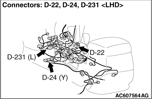
STEP 1. Connector check: D-22 joint connector (CAN2) and D-24 SRS-ECU
connector
|
|
|
| caution |
The strand end of the twist wire should be within
10 cm from the connector. For details refer to  . .
|
|
|
|
When checking the joint connector, ensure that
its wiring harness side and its short pins are not damaged.
|
|
|
Q.
Is the check result normal?
|
|
|
 Go to Step 2. Go to Step 2.
|
|
|
|
|
|
 Repair
the defective connector. Replace the joint connector as necessary. Repair
the defective connector. Replace the joint connector as necessary.
|
|
|
|
|
|
STEP 2. Resistance measurement at D-22 joint connector (CAN2) and D-24
SRS-ECU connector.
|
|
|
| caution |
A digital multimeter should be used. For details
refer to .
|
|
|
|
| caution |
The test wiring harness should be used. For details
refer to .
|
|
|
|
(1)Disconnect joint connector (CAN2) and the SRS-ECU
connector, and measure at the wiring harness side.
|
|
|
(2)Turn the ignition switch to the LOCK (OFF)
position.
|
|
|
(3)
| caution |
When measuring the resistance, disconnect the
negative battery terminal. For details refer to .
|
Ensure that the negative battery terminal is disconnected.
|
|
|
(4)Continuity between D-22 joint connector (CAN2) terminal
No.3 and D-24 SRS-ECU connector terminal No.32
OK: Continuity
(2 Ω or less)
|
|
|
(5)Continuity between D-22 joint connector (CAN2) terminal
No.9 and D-24 SRS-ECU connector terminal No.43
OK: Continuity
(2 Ω or less)
| caution |
Strictly observe the specified wiring harness repair
procedure. For details refer to .
|
|
|
|
Q.
Is the check result normal?
|
|
|
<All the resistances measure 2
Ω or less> Power supply to the SRS-ECU may be suspected.
Diagnose the SRS-ECU. Refer to .
|
|
|
|
|
|
NO : <Either or all of the resistances
measure more than 2 Ω> Check the intermediate connector D-231,
and repair if necessary. If the intermediate connector is normal, repair
the wiring harness between joint connector (CAN2) and the SRS-ECU
connector.
|
|
|
|