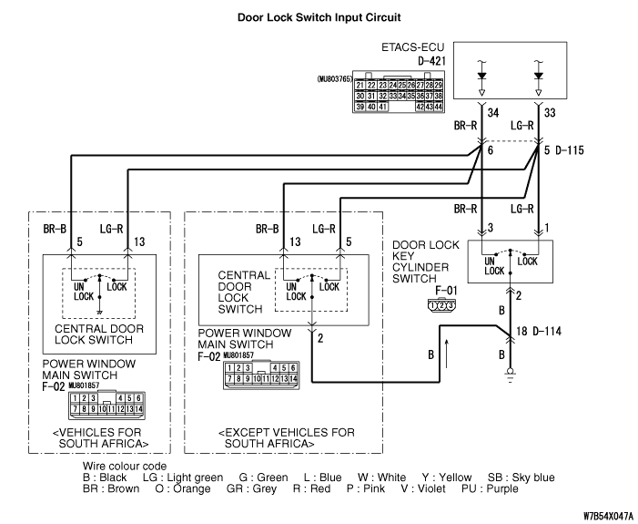
Inspection Procedure C-16: The signal from the central door lock switch
(incorporated with the power windows main switch or door lock key cylinder
switch) is not received. <RHD>


|
|
| caution |
Whenever the ECU is replaced, ensure that the input
signal circuit is normal.
|
|
|
|
COMMENTS ON TROUBLE SYMPTOM
|
|
|
Input signal from the central door lock switch
(incorporated with the power window main switch or door lock key cylinder
switch) and door lock key slangier are used to operate the central door
locking function. If the signal is abnormal, the central door locking
function will not work normally.
|
|
|
- Malfunction of the power window main switch
- Malfunction of the door lock key cylinder
- Malfunction of the ETACS-ECU
- Damaged harness wires and connectors
|
|
|
STEP 1. Trouble spot determination
|
|
|
Q.
Which signal is not sent?
|
|
|
The signal is not sent from the power window
main switch. <Except vehicles for South Africa> : Go to Step 2. : Go to Step 2.
|
|
|
|
|
|
The signal is not sent from the power window
main switch. <Vehicles for South Africa> : Go to Step 8.
|
|
|
|
|
|
The signal is not sent from the door lock key
cylinder. : Go
to Step 12.
|
|
|
|
|
|
STEP 2. Connector check: F-02 power window main switch
connector
|
|
|
Q.
Is the check result normal?
|
|
|
 Go to Step 3. Go to Step 3.
|
|
|
|
|
|
 Repair
the defective connector. Repair
the defective connector.
|
|
|
|
|
|
STEP 3. Check the central door lock switch (incorporated with the power
window main switch).
|
|
|
Refer to GROUP 42 - Door handle and latch
 . .
|
|
|
Q.
Is the check result normal?
|
|
|
Go to Step 4.
|
|
|
|
|
|
Replace the power window main
switch.
|
|
|
|
|
|
STEP 4. Resistance measurement at the F-02 power window main switch
connector.
|
|
|
(1)Disconnect the connector, and measure at the wiring
harness side.
|
|
|
(2)Resistance between F-02 power window main switch connector
terminal No.2 and body earth
OK: Continuity exists (2 Ω
or less)
|
|
|
Q.
Is the check result normal?
|
|
|
Go to Step 6.
|
|
|
|
|
|
Go to Step 5.
|
|
|
|
|
|
STEP 5. Check the wiring harness between F-02 power window main switch
connector terminal No.2 and body earth.
|
|
|
| note |
Prior to the wiring harness inspection, check
intermediate connector D-114, and repair if necessary.
|
|
|
|
- Check the earth wires for open circuit.
|
|
|
Q.
Is the check result normal?
|
|
|
Intermittent malfunction (Refer to
GROUP 00 - How to Cope with Intermittent Malfunction ).
|
|
|
|
|
|
Repair
the wiring harness.
|
|
|
|
|
|
STEP 6. Connector check: D-421 ETACS-ECU connector
|
|
|
Q.
Is the check result normal?
|
|
|
Go to Step 7.
|
|
|
|
|
|
Repair
the defective connector.
|
|
|
|
|
|
STEP 7. Check the wiring harness between F-02 power window main switch
connector terminal Nos.5, 13 and D-421 ETACS-ECU connector terminal Nos.
33, 34.
|
|
|
| note |
Prior to the wiring harness inspection, check
intermediate connector D-115, and repair if necessary.
|
|
|
|
- Check the input line for open circuit.
|
|
|
Q.
Is the check result normal?
|
|
|
Go to Step 18.
|
|
|
|
|
|
Repair
the wiring harness.
|
|
|
|
|
|
STEP 8. Connector check: F-02 power window main switch
connector
|
|
|
Q.
Is the check result normal?
|
|
|
Go to Step 9.
|
|
|
|
|
|
Repair
the defective connector.
|
|
|
|
|
|
STEP 9. Check the central door lock switch (incorporated with the power
window main switch).
|
|
|
Refer to GROUP 42 - Door handle and latch
.
|
|
|
Q.
Is the check result normal?
|
|
|
Go to Step 10.
|
|
|
|
|
|
Replace the power window main
switch.
|
|
|
|
|
|
STEP 10. Connector check: D-421 ETACS-ECU connector
|
|
|
Q.
Is the check result normal?
|
|
|
Go to Step 11.
|
|
|
|
|
|
Repair
the defective connector.
|
|
|
|
|
|
STEP 11. Check the wiring harness between F-02 power window main switch
connector terminal Nos.5, 13 and D-421 ETACS-ECU connector terminal Nos.
33, 34.
|
|
|
| note |
Prior to the wiring harness inspection, check
intermediate connector D-115, and repair if necessary.
|
|
|
|
- Check the input line for open circuit.
|
|
|
Q.
Is the check result normal?
|
|
|
Go to Step 18.
|
|
|
|
|
|
Repair
the wiring harness.
|
|
|
|
|
|
STEP 12. Connector check: F-01 door lock key cylinder switch
connector
|
|
|
Q.
Is the check result normal?
|
|
|
Go to Step 13.
|
|
|
|
|
|
Repair
the defective connector.
|
|
|
|
|
|
STEP 13. Check the door lock key cylinder switch.
|
|
|
Refer to GROUP 42 - Door handle and latch
.
|
|
|
Q.
Is the check result normal?
|
|
|
Go to Step 14.
|
|
|
|
|
|
Replace the power window main
switch.
|
|
|
|
|
|
STEP 14. Resistance measurement at the F-01 door lock key cylinder
switch connector.
|
|
|
(1)Disconnect the connector, and measure at the wiring
harness side.
|
|
|
(2)Resistance between F-01 door lock key cylinder switch
connector terminal No.2 and body earth
OK: Continuity exists (2
Ω or less)
|
|
|
Q.
Is the check result normal?
|
|
|
Go to Step 16.
|
|
|
|
|
|
Go to Step 15.
|
|
|
|
|
|
STEP 15. Check the wiring harness between F-01 door lock key cylinder
switch connector terminal No.2 and body earth.
|
|
|
| note |
Prior to the wiring harness inspection, check
intermediate connector D-114, and repair if necessary.
|
|
|
|
- Check the earth wires for open circuit.
|
|
|
Q.
Is the check result normal?
|
|
|
Intermittent malfunction (Refer to
GROUP 00 - How to Cope with Intermittent Malfunction ).
|
|
|
|
|
|
Repair
the wiring harness.
|
|
|
|
|
|
STEP 16. Connector check: D-421 ETACS-ECU connector
|
|
|
Q.
Is the check result normal?
|
|
|
Go to Step 17.
|
|
|
|
|
|
Repair
the defective connector.
|
|
|
|
|
|
STEP 17. Check the wiring harness between F-01 door lock key cylinder
switch connector terminal Nos.1, 3 and D-421 ETACS-ECU connector terminal
Nos.33, 34.
|
|
|
| note |
Prior to the wiring harness inspection, check
intermediate connector D-115, and repair if necessary.
|
|
|
|
- Check the input line for open circuit.
|
|
|
Q.
Is the check result normal?
|
|
|
Go to Step 18.
|
|
|
|
|
|
Repair
the wiring harness.
|
|
|
|
|
|
STEP 18. ETACS switch data by using the SWS monitor
|
|
|
Check the input signal from the central door
lock switch (incorporated with the power windows main switch or door lock
key cylinder switch).
|
|
|
- Door lock switch: Neutral to lock
|
|
|
Item No.
|
Item name
|
Normal
condition
|
Item 26
|
Centre door lock
switch
|
ON (only when operated to
lock)
|
Item 27
|
Centre door unlock
switch
|
OFF
|
|
|
|
- Door lock switch: Neutral to unlock
|
|
|
Item No.
|
Item name
|
Normal
condition
|
Item 26
|
Centre door lock
switch
|
OFF
|
Item 27
|
Centre door unlock
switch
|
ON (only when operated to
unlock)
|
|
|
|
OK: Normal conditions are displayed
for all the items.
|
|
|
Q.
Are the check result normal?
|
|
|
The
trouble can be an intermittent malfunction (Refer to GROUP 00 - How
to Cope with Intermittent Malfunction ).
|
|
|
|
|
|
Replace the ETACS-ECU.
|
|
|
|