REMOVAL AND INSTALLATION <4M4>


Pre-removal Operation
  • Refrigerant Discharging (Refer to ).
  • Engine room under cover front (Refer to GROUP 51, Under cover ).
  • Intercooler air hose B (Refer to GROUP 15, Intercooler ).

Post-installation Operation
  • Refrigerant Charging (Refer to ).
  • Drive Belt Tension Adjustment (Refer to GROUP 11E, On-vehicles Service - Compressor Drive Belt Tension Check <4M40> or GROUP 11G, On-vehicles Service - Drive Belt Tension Check <4M41> ).
  • Engine room under cover front (Refer to GROUP 51, Under cover ).
  • Intercooler air hose B (Refer to GROUP 15, Intercooler ).


Removal steps
<<A>>

1.
Flexible suction hose connection
<<A>>

2.
Flexible discharge hose connection


3.
O-ring
<<B>>

4.
Compressor drive belt


·
Power steering oil reservoir bracket
<<C>>
>>A<<
5.
A/C compressor assembly


6.
A/C compressor bracket


7.
Tension pulley

REMOVAL SERVICE POINTS


<<A>> FLEXIBLE SUCTION HOSE AND FLEXIBLE DISCHARGE HOSE DISCONNECTION


caution Use the plug which is not breathable because A/C compressor oil or receiver have high hygroscopicity.
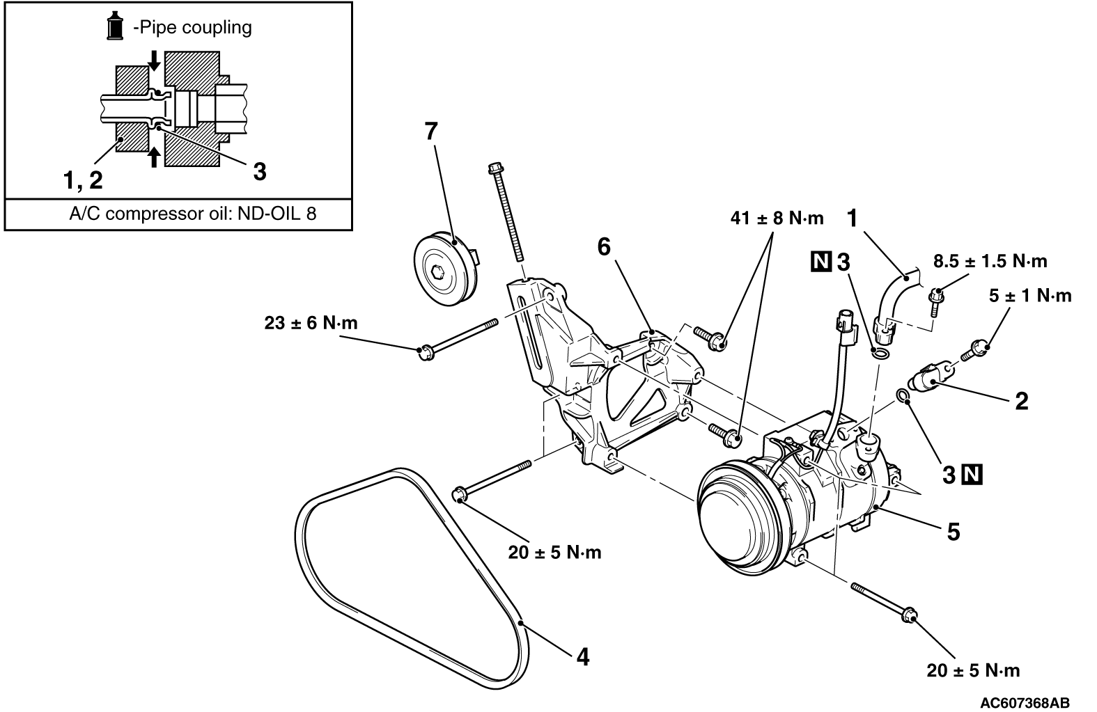
Plug the hose nipple removed to prevent the entry of dust and dirt.

<<B>> A/C COMPRESSOR DRIVE BELT REMOVAL


Refer to GROUP 14, Radiator fan .

<<C>> COMPRESSOR REMOVAL


Be careful not to spill the A/C compressor oil and remove the A/C compressor.

INSTALLATION SERVICE POINT


>>A<< A/C COMPRESSOR INSTALLATION


When installing the new A/C compressor, install the A/C compressor after adjusting the oil volume as follows.

  1. Measure the oil of A/C compressor removed. (X cm3)
  2. Drain the oil (Y cm3) given by the following expression from a new A/C compressor, and then install the A/C compressor.
    160 cm3 - X cm3 = Y cm3
    note
    1. 160 cm3 shows the oil volume contained in the new A/C compressor.
    2. Y cm3 shows the oil volume stored in the refrigerant line, condenser, and cooling unit, etc.