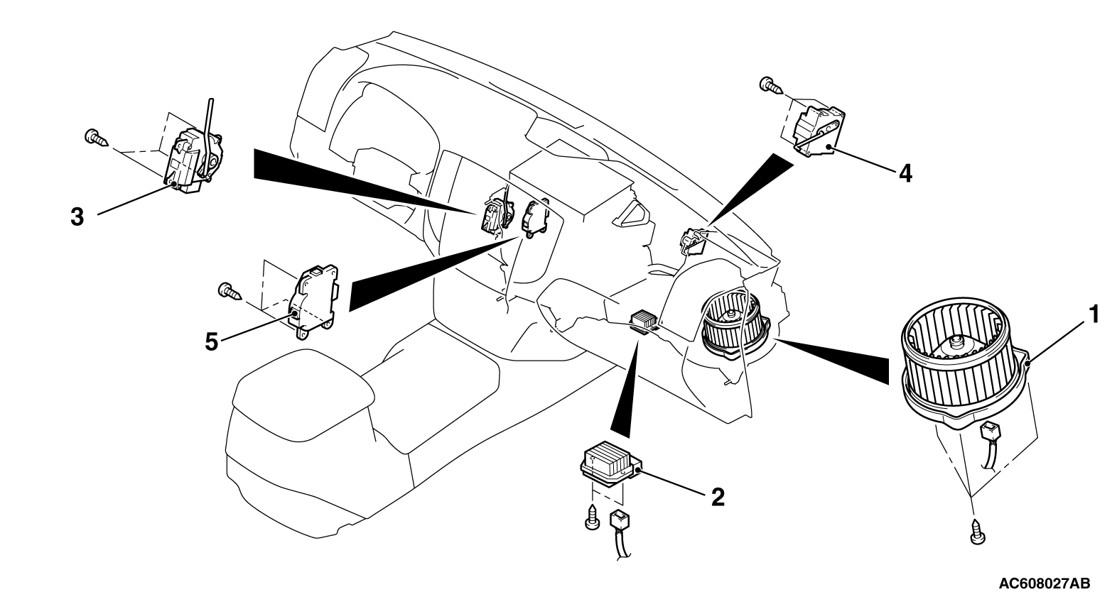
| Front blower motor removal
steps |
|||
| · |
Passenger side under cover (Refer
to GROUP 52A - Instrument Panel  ) ) |
||
| 1. |
Front
blower motor |
||
| Power transistor removal
steps |
|||
| · |
Passenger side under cover (Refer
to GROUP 52A - Instrument Panel ) |
||
| 2. |
Power
transistor |
||
| Front mode selection damper
control motor and potentiometer removal
steps |
|||
| · |
Passenger side under cover (Refer
to GROUP 52A - Instrument Panel ) |
||
| · |
Foot
duct (Refer to ) |
||
| >>C<< |
3. |
Front
mode selection damper control motor and
potentiometer |
|
| Front air mixing damper control
motor and potentiometer removal
steps |
|||
| · |
Passenger side under cover (Refer
to GROUP 52A - Instrument Panel ) |
||
| >>B<< |
4. |
Front
air mixing damper control motor and
potentiometer |
|
| Outside/inside air selection
damper control motor removal
steps |
|||
| · |
Passenger side under cover (Refer
to GROUP 52A - Instrument Panel ) |
||
| <<A>> |
>>A<< |
5. |
Outside/inside air selection
damper control motor |


