|
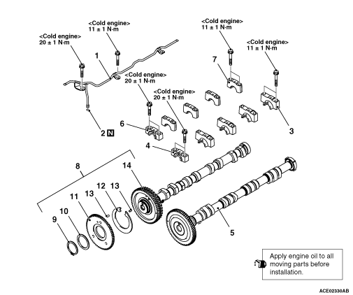
Loosen the camshaft bearing cap
mounting bolts in the order of number shown in the figure in
four or five steps, and remove the camshaft bearing
caps.
|
|
|
1.Fix the exhaust camshaft
hexagonal area using a vice or other devices.
|

|
2.Press fit the dowel pin
into the exhaust camshaft and sub gear so that the dimension
becomes as shown in the figure.
|

|
3.After contacting the
C-spring with the dowel pin as shown in the figure, set to
the exhaust camshaft.
|

|
4.Set the sub gear to the
exhaust camshaft so that the sub gear dowel pin is inside
the A range between the C-spring and exhaust camshaft dowel
pin as shown in the figure.
5.Assemble the wave
washer and the snap ring to the exhaust camshaft.
|
|
|
1.Fix the hexagonal area of
exhaust camshaft assembly using a vice or other
devices.
|

|
2.
| caution |
Avoid turning the sub gear
than necessary.
|
Set the flange bolts (M6 x 12) to 2 locations of sub
gear. Then, using a screwdriver, turn the sub gear clockwise
until the sub gear hole (M7) and the threaded hole (M6) of
exhaust camshaft gear match as shown in the figure.
|

|
3.Temporarily fix the sub
gear using the bolt (M6 x 12). At this time, screw in until
the bolt head is in contact with the sub
gear.
4.Remove the 2 flange bolts (M6 x 12)
installed in the step 2.
5.Remove from the vice or
other devices the exhaust camshaft assembly to which the sub
gear being temporarily fixed. Then, apply the engine oil to
the cam face, journal section, thrust face, and gear teeth
face of exhaust camshaft assembly.
|

|
6.Set the timing marks of
the exhaust camshaft and inlet camshaft in the position
shown in the illustration.
|

|
1.Be careful not to confuse
the camshaft bearing cap No. and its identification
mark.
2.Install the O-ring into the inlet oil
pipe, taking care not to damage or twist
it.
3.Install the inlet oil pipe to the camshaft
bearing cap.
|

|
4.Tighten each camshaft
bearing cap mounting bolts to the specified torque in the
order of number shown in the figure in two or three
steps.
Tightening
torque:
M6: 11 ±
1 N·m
M8: 20 ±
1 N·m
|
 ).
).