
|
Use special tool oil filter wrench
(MH061590) or commercially-available tool to remove
the oil filter.
|

|
Use special tool oil pressure
switch wrench (MD998012) to remove the engine oil pressure
switch.
|

|
Use special tool oil pressure
switch wrench (MB992118) to remove the engine oil pressure
switch.
|
|
|
1.Remove the oil pan
mounting bolts.
|

|
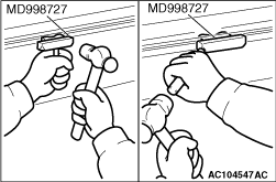
2.
| caution |
Do not use special tool oil
pan FIPG cutter (MD998727) in area A of the
oil pan. Using the special tool in area A may
cause deformation of the front case because the
front case is made of aluminium.
|
Tap the special tool into the range (B) between the
cylinder block and the oil pan, and
then slide the special tool sideways.
| note |
If any surrounding parts
interfere with the removal, there is no need to
use the special
tool.
|
3.Remove the oil pan.
|

|
1.Remove the plug on the
right side of cylinder block.
2.Insert a phillips
screwdriver into the plug hole to lock the silent shaft in
position.
3.Remove the flange bolt.
|

|
Put alignment marks on the inner
and outer rotors for reference in reassembly.
|
|
|
1.Apply engine oil to the
balancer shaft drive and driven gears.
|

|
2.Install the balancer shaft
drive and driven gears to the front lower case. Make sure
that
the alignment marks are in line.
|
|
Install the outer rotor in the same
direction as before noting the mark put at the time
of removal. Apply engine oil to the entire rotor
surface.
|
|
|
1.Apply engine oil to the
oil seal outer surface.
|

|
2.Using special tool
balancer shaft drive gear oil seal guide (MD998385), drive
in with
a socket wrench.
|

|
1.Attach special tool
crankshaft front oil seal guide (MD998383) to the crankshaft
and apply
engine oil to the outer surface of the
tool.
2.Using special tool crankshaft front oil
seal installer (MD998382), install the front
oil seal into the front lower case.
|

|
1.Insert a phillips
screwdriver into the plug hole to block the balancer
shaft.
2.Install the flange bolt and tighten to
the specification.
3.Remove the screwdriver and
install the plug.
|

|
Apply engine oil to the oil seal
outer surface and drive in with a socket wrench.
|
|
|
Use either an oil pan gasket or a
sealant for installing the oil pan. Install the oil
pan in accordance with the following procedure
respectively.
|

|
1.<Sealant>
(1)
Remove sealant from the oil pan and cylinder block
surfaces.
(2)
Apply a Φ4 ± 1 mm wide bead of sealant to the
entire circumference of
the oil pan flange.
Specified sealant:
ThreeBond 1217G or equivalent
|
|
| note |
Install the oil
pan immediately applying
sealant.
|
|
(3)
|
|
| caution |
After the
installation, until a sufficient
period of
time (one hour or more) elapses, do
not apply the oil or water to the
sealant application area
or start the engine.
|
|
Install the oil pan.
(4)
Tighten the oil pan bolts to the specified
torque.
Tightening torque: 9.0 ± 3.0
N·m
2.<Gasket>
(1)
Remove sealant from the oil pan and cylinder block
surfaces.
(2)
Install the oil pan gasket so that its fluorine-coated
surface faces the cylinder
block side.
(3)
Install the oil pan.
(4)
Tighten the oil pan bolts to the specified
torque.
Tightening torque: 9.0 ± 3.0
N·m
|

|
Position the tab as shown in the
illustration.
|

|
1.
| caution |
Use care not to allow the
sealant to plug the oil passage.
|
Apply sealant to the engine oil pressure switch
thread.
Specified sealant: ThreeBond 1141J or
equivalent
| note |
Install the engine oil
pressure switch immediately after applying
sealant.
|
2.
| caution |
After the installation, until
a sufficient period of
time (one hour or more) elapses, do not apply
the oil or water to the sealant application area
or start the engine.
|
In the same manner as removal, use special tool oil
pressure switch wrench (MB992118)
to tighten the engine oil pressure switch to the specified
torque.
Tightening torque: 10 ± 2
N·m
|


|
1.
| caution |
Do not get any oil (rust
prevention oil etc.) on the area as shown in the
figure to prevent
the influence of switch function.
|
| caution |
Use care not to allow the
sealant to plug the oil passage.
|
Apply sealant to the engine oil pressure switch
thread.
Specified sealant: ThreeBond 1141J or
equivalent
| note |
Install the engine oil
pressure switch immediately after applying
sealant.
|
2.
| caution |
After the installation, until
a sufficient period of
time (one hour or more) elapses, do not apply
the oil or water to the sealant application area
or start the engine.
|
In the same manner as removal, use special tool oil
pressure switch wrench (MD998012)
to tighten the engine oil pressure switch to the specified
torque.
Tightening torque: 10 ± 2
N·m
|

|
1.Install the engine oil
pressure switch terminal in the direction shown in the
illustration.
2.Tighten the engine oil pressure
switch terminal mounting screw to the specified
torque.
Tightening torque: 3.5 ± 0.4
N·m
|
|
|
1.Clean the oil filter
installing surface on the cylinder block side.
|

|
2.Apply a small amount of
engine oil to the new oil filter gasket.
3.For the
specified tightening torque, refer to the caution label
attached on the oil
filter.
4.Tighten the oil filter until the gasket
contacts with the installation surface.
5.In the
same manner as removal, use special tool oil filter wrench
(MH061590) or commercially-available
tool to tighten the oil filter to the specified
torque.
|

