
|
Using general service tool, remove
the oil filter from the oil filter bracket.
|

|
1.Remove the oil pan
bolts.
2.Insert the special tool Oil pen remover
(MD998727) into the joint between the cylinder
block and oil pan by tapping the tool with a
hammer.
3.Remove the oil pan by tapping an edge of
the special tool Oil pen remover (MD998727)
with a hammer to move it sideways.
|

|
Fit the teeth of the special tool
in notches of the plug as shown in the
drawing and support the tool with the special tool to loosen
the plug.
- Plug wrench (MD998162)
- Plug wrench retainer (MD998783)
|

|
1.Remove the plug on the
side of the cylinder block.
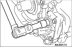
2.Insert a Phillips
screwdriver (shank diameter 8 mm) into the plug hole to lock
the
counterbalance shaft.
|
|
3.Loosen the flange
bolt.
|

|
| caution |
Be sure to remove the front
bearing first. If it has not
been removed, special tool Silent shaft bearing
puller (MD998372) cannot be used for rear
balance
shaft bearing removal.
|
Using special tool Silent shaft bearing puller
(MD998371), remove the counterbalance shaft
front bearing from the cylinder block.
|


|
1.Using special tool Silent
shaft bearing puller (MD998372), remove the right
counterbalance
shaft rear bearing from the cylinder block.
Using special
tools, remove the left counterbalance shaft rear bearing
from the cylinder
block.
- Silent shaft bearing puller (MD998372)
- Bearing installer stopper (MB991603)
|


|
1.Install special tool
Silent shaft bearing installer stopper (MB991603) to the
cylinder
block.
2.Apply engine oil to the rear bearing
outer surface and bearing hole in the cylinder
block.
3.Using special tool Silent shaft bearing
installer (MD998705), install the rear bearing.
| note |
The left rear bearing has no
oil holes.
|
|

|
1.Install special tool the
guide pin of the Silent shaft bearing installer (MD998705)
in
the threaded hole of the cylinder block as shown.
|

|
2.Align the ratchet ball of
the special tool with the oil hole in the rear bearing to
install
the bearing of the special tool.
3.Apply engine
oil to the bearing outer surface and bearing hole in the
cylinder block.
|


|
4.Using special tool,
install the rear bearing. Make sure that the oil hole of the
bearing
is aligned with the oil hole of the cylinder block.
|

|
1.Remove the rear bearing
installing portion from the special tool Silent shaft
bearing
installer (MD998705).
|
|
2.Install special tool the
guide pin of the Silent shaft bearing installer (MD998705)
in
the threaded hole of the cylinder block as shown.
|

|
3.Align the ratchet ball of
the special tool with the oil hole in the rear bearing to
install
the bearing of the special tool.
4.Apply engine
oil to the front bearing outer surface and bearing hole in
the cylinder.
|

|
5.Using special tool,
install the rear bearing. Make sure that the oil hole of the
bearing
is aligned with the oil hole of the cylinder block.
|

|
Using a suitable socket wrench,
install the counterbalance shaft oil seal into the front
case.
|

|
Using a suitable socket wrench,
install the oil pump oil seal into the front case.
|

|
Using special tool Crankshaft front
oil seal installer (MD998375), install the crankshaft
front oil seal into the front case.
|
|
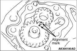
Install the oil pump gears into the
front case and align the alignment marks.
|

|
1.Set special tool
Crankshaft front oil seal guide (MD998258) on the front end
of crankshaft
and apply a thin coat of engine oil to the outer surface of
special tool.
2.Apply engine oil to the lip of the
crankshaft front oil seal.
|

|
3.Install the front case
carefully not to damage the oil seal.
|

|
4.
| caution |
Carefully install the
tightening bolts because of the different
length respectively.
|
Tighten all flange bolts to the specified
torque.
Tightening torque: 23 ± 3
N·m
|
|
1.Insert a Phillips head
screwdriver (shank diameter 8 mm) into the hole in the left
side
of the cylinder block to lock the counterbalance
shaft.
|

|
2.Secure the oil pump driven
gear onto the left counterbalance shaft by tightening the
flange
bolt to the specified torque.
Tightening
torque: 36 ± 3 N·m
3.Pull out
the screwdriver and screw in the plug.
|

|
1.Install a new O-ring to
the groove of the front case.
2.Install the plug
to the front case.
3.Use the special tool to
tighten the plug to the specified torque.
- Plug wrench (MD998162)
- Plug wrench retainer (MD998783)
Tightening torque: 23 ± 3
N·m
|
|
|
1.
| caution |
Do not apply FIPG over
remaining old FIPG. Doing so could
result in oil leakage.
|
Thoroughly remove old FIPG from the gasket surfaces
of the cylinder block and oil pan.
|

|
2.
| caution |
Too much FIPG will squeeze
out, blocking coolant or oil passages,
while too thin a bead could result in
leakage.
|
Apply a 4 mm diameter bead of FIPG to the flange
surface all around the oil pan.
Specified
sealant:
Mitsubishi Genuine Part
No.MD970389 or equivalent
| note |
In the grooved areas on the
oil pan flange, apply FIPG bead along the center
of the groove.
|
|

|
3.Install the shorter bolts
in the locations indicated in the drawing.
|
|
|
1.Clean the installation
surface of the filter bracket.
|

|
2.Apply engine oil to the
o-ring of the oil filter.
|

|
3.Using general service
tool, Install the oil filter to the bracket and tighten it
to the
specified torque.
Tightening
torque
Part number MD356000 filter: 14
± 2 N·m
Other Mitsubishi Genuine
filter: 17 ± 3
N·m
4.If a torque wrench
cannot be used use the following procedure:
(1)
Screw in the oil filter until its o-ring contacts the oil
filter bracket.
(2)
Tighten the oil filter as follows:
Mitsubishi
Genuine filter: 3/4 turn
|

|
| caution |
If the gasket is installed in
the wrong direction, oil leaks will
occur.
|
Install the drain plug gasket in the direction
shown.
|

