|
|
If all the turn-signal lamps do not illuminate,
the ignition switch (IG1), the turn-signal
lamp switch input circuit or the ETACS-ECU may be defective.
|
|
|
- Malfunction of the column switch
- Malfunction of the ETACS-ECU
- Damaged harness wires and connectors
|
|
|
Check that the power supply and earth lines to
the ETACS-ECU and the SWS communication
lines are normal.
|
|
|
OK: "OK" is displayed on the
"ETACS ECU" menu.
|
|
|
Q.
Is the check result normal?
|
|
|
 Refer
to Inspection Procedure A-3 "Communication with the ETACS-ECU is not
possible Refer
to Inspection Procedure A-3 "Communication with the ETACS-ECU is not
possible  ." ."
|
|
|
|
|
|
Check that the hazard warning lamps illuminate
normally.
|
|
|
Q.
Is the check result normal?
|

|
Q.
Is the check result normal?
 Go to Step 4. Go to Step 4.
Repair the defective
connector.
|
|
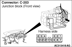
(1)Remove the ETACS-ECU, and measure at the
junction block side.
|

|
(2)Voltage between C-219 ETACS-ECU connector
terminal No.11 and body earth
OK: System voltage
Q.
Is the check result normal?
Go to Step 8.
Go to Step
5.
|

|
| note |
Prior to the wiring harness inspection, check
intermediate connector C-125 and junction
block connector C-203, and repair if necessary.
|
- Check the power supply line for open circuit.
Q.
Is the check result normal?
Go to Step 8.
Repair the wiring
harness.
|
|
|
Check the SWS communication signal, which are
related to the right turn-signal lamps.
|
|
|
<Selected item> TURN SIGNAL -
TURN-SIG. RH
- Turn-signal lamp switch: RH
- Ignition switch: ON
|
|
|
OK: Normal conditions are displayed
for all the items
|
|
|
Q.
Is the check result normal?
|
|
|
Normal conditions are displayed for all the
items. : Go to
Step 7. : Go to
Step 7.
|
|
|
|
|
|
Normal condition is not displayed for item 10
or 11. : Refer to inspection procedure P-5 "Column switch (lighting and
turn-signal lamp switch)
signal is not received ."
|
|
|
|
|
|
Normal condition is not displayed for item
No.30. : Refer to inspection procedure P-2 "The ignition switch (IG1)
signal is not received ."
|
|
|
|
|
|
Check the SWS communication signal, which are
related to the left turn-signal lamps.
|
|
|
<Selected item> TURN SIGNAL -
TURN-SIG. LH
- Turn-signal lamp switch: LH
- Ignition switch: ON
|
|
|
OK: Normal conditions are displayed
for all the items.
|
|
|
Q.
Is the check result normal?
|
|
|
Normal conditions are displayed for all the
items. : Go to
Step 8.
|
|
|
|
|
|
Normal condition is not displayed for item 10
or 11. : Refer to inspection procedure P-5 "Column switch (lighting and
turn-signal lamp switch)
signal is not received ."
|
|
|
|
|
|
Check that the turn-signal lamps
illuminate.
|
|
|
Q.
Is the check result normal?
|
|
|
The
trouble can be an intermittent malfunction (Refer to GROUP 00 - How
to Cope with Intermittent Malfunction ).
|
|
|
|
