|
|
The interior lamp
automatic-shutdown function operates in accordance with the
interior
lamp loaded signal. If this signal is abnormal, the
functions below will not work normally.
|
|
|
- Ignition key cylinder illumination lamp
- Room lamps
|
|
|
- Malfunction of the ETACS-ECU
- Damaged wiring harness or connector(s)
|
|
|
When the ignition switch is turned
to the LOCK (OFF) position, check if the hazard warning
lamps illuminate.
|
|
|
Q.
Is the check result normal?
|
|
|
 Refer to inspection
procedure A-2 "Check the ETACS-ECU battery power supply
circuit Refer to inspection
procedure A-2 "Check the ETACS-ECU battery power supply
circuit  ." ."
|
|
|
|


|
Q.
Is the check result normal?
 Go to Step
3. Go to Step
3.
Repair
the defective connector.
|
|
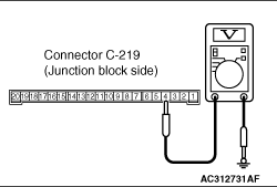
(1)Remove the ETACS-ECU, and
measure at the junction block side.
(2)Turn the ignition
switch to the ON position.
|

|
(3)Voltage between C-219 ETACS-ECU
connector terminal No.8 and body earth
OK:
System voltage
Q.
Is the check result normal?
Go to Step
5.
Go to Step
4.
|


|
| note |
Prior to the wiring harness
inspection, check junction block connector
C-202, and repair
if necessary.
|
- Check the power supply line to the ignition switch
(IG1) for open circuit.
Q.
Is the check result normal?
The trouble can be
an intermittent malfunction (Refer to GROUP 00 - How
to Cope with Intermittent Malfunction ).
Repair the wiring
harness.
|
|
(1)Remove the ETACS-ECU, and
measure at the junction block side.
(2)Turn the ignition
switch to the ACC position.
|
|
(3)Voltage between terminal 4 and
body earth
OK: System voltage
Q.
Is the check result normal?
Go to Step
7.
Go to Step
6.
|


|
| note |
Prior to the wiring harness
inspection, check joint connector C-32 <LH
drive
vehicles>, C-01 <RH drive
vehicles> junction block connector C-203
or intermediate connector C-125, and repair if
necessary.
|
- Check the power supply line to the ignition switch
(ACC) for open circuit.
Q.
Is the check result normal?
The trouble can be
an intermittent malfunction (Refer to GROUP 00 - How
to Cope with Intermittent Malfunction ).
Repair the wiring
harness.
|
|
|
Check that the interior lamp loaded
signal is received normally.
|
|
|
Q.
Is the check result normal?
|
|
|
The trouble can be
an intermittent malfunction (Refer to GROUP 00 - How
to Cope with Intermittent Malfunction ).
|
|
|
|
