|
1.
| caution |
Never turn the crankshaft
anti-clockwise.
|
Turn the crankshaft clockwise, align the mating
marks on the camshaft sprocket with the
brilliant white mark ring plates on the timing chain to set
No. 1 cylinder to TDC (Top Dead Centre)
of its compression stroke.
|

|
2.
| caution |
- Do not lock the camshaft using the
timing chain.
- The camshaft sprocket bolt is left
threaded, so the arrow indicating its
tightening direction
is marked on the bolt head. To loosen
this bolt, turn the bolt to the opposite
direction of
the arrow.
- The timing chain must be attached to the
camshaft sprocket.
|
Hold the hexagonal part of the camshaft with an open
end wrench, loosen the camshaft sprocket
bolt, and then remove the camshaft sprocket with the timing
chain still attached.
3.Tie up the timing chain
and the camshaft sprocket with a cord to prevent the mating
mark misalignment.
|

|
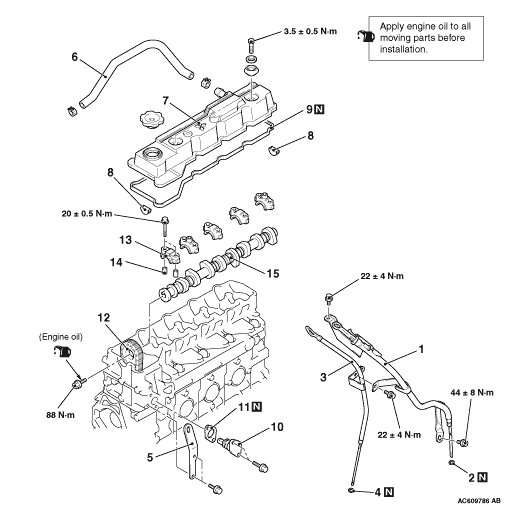
1.The camshaft numbers are
embossed on the top of the camshaft caps. Install the
camshaft
caps in that order so that their front marks face the
direction shown.
2.Tighten the camshaft cap
mounting bolts to the specified
torque.
Tightening torque: 20 ±
0.5 N·m
|
|
|
1.Install the camshaft
sprocket to the camshafts with the timing chain
attached.
|
|
2.Hold the hexagonal part of
the camshaft with an open end wrench in the same manner as
removal.
3.Apply a small amount of engine oil to
the camshaft sprocket bolt thread and the flange,
and then tighten to the specified
torque.
Tightening torque: 88
N·m
|

|
Place the timing chain tensioner
gasket with its silicone print facing toward the timing
chain tensioner side.
|

|
1.Raise the cam, and then
push in the plunger, and lock the plunger using a
hook.
2.
| caution |
To install the timing chain
tensioner, always push in the plunger. If
you fail to do this, the timing chain will be
excessively tensioned, causing damage.
|
Install the timing chain tensioner to the cylinder
head.
3.
| caution |
If the crankshaft is turned
anti-clockwise after the timing chain tensioner
is installed, the plunger will be excessively
tensioned, causing the plunger to go beyond the
cam inside the timing chain tensioner.
|
Turn the crankshaft clockwise.
| note |
If the crankshaft is turned
clockwise after the timing chain tensioner is
installed, the plunger
is automatically unhooked. Then its internal
ratchet mechanism adjusts the timing chain
tension.
|
|

|
1.Apply the specified
sealant to the camshaft end seal mating surface as
shown.
Specified sealant: MITSUBISHI GENUINE
PART MD970389 or equivalent
| note |
Install the camshaft end seal
and rocker cover assembly within 15 minutes
after applying sealant.
|
2.Install the camshaft end seal to the
cylinder head.
|
 ).
).