
|
1.Remove the input shaft
speed sensor.
|

|
2.Remove the output shaft
speed sensor.
|

|
3.Remove the manual control
lever, and then remove the inhibitor switch.
|

|
4.Remove the snap ring, and
remove the parking gear using a puller (corresponding load
approximately
9,800 N).
|

|
5.
| caution |
Carefully hammer the special
tool so that the oil pan mounting
surface is not damaged.
|
Remove the twenty oil pan mounting bolts and then
use the special tool Oil pan FIPG cutter
(MD998727) to remove the oil pan.
|

|
6.Remove the oil filter and
O-ring.
|

|
7.Remove the detent
spring.
|

|
8.Disconnect the valve body
harness connectors.
|


|
9.Remove the twenty valve
body mounting bolts and then remove the valve body, O-ring
and
oil temperature sensor.
| note |
The twenty valve body mounting
bolts are plated bolts.
|
| note |
The O-ring is mounted on the
transmission case side as shown in the
illustration. However
there may be cases when it will come off with
the valve body.
|
|

|
10.Remove the snap ring and
disconnect the solenoid valve harness.
|

|
11.Remove the oil strainer
and two oil seals.
|

|
12.Remover each accumulator
piston, seal ring and spring.
|
|
No.
|
Name
|
1
|
For overdrive
clutch
|
2
|
For second
brake
|
3
|
For low/reverse
brake
|
4
|
For underdrive
clutch
|
|
| note |
To make assembly easier,
attach an identification tag on the removed
accumulator piston.
|
|

|
13.Remove the detent lever
spring pin.
|

|
14.Remove the pin, and then
remove the manual control shaft, two O-rings, detent lever
and
parking roller rod.
|

|
15.Remove the eight
converter housing mounting bolts, and then the converter
housing.
|

|
16.Remove the ten oil pump
mounting bolts.
17.Install special tool Oil pump
remover (MD998333) into the bolt hole shown in the
illustration.
|

|
18.While screwing in special
tools Oil pump remover (MD998333) evenly, remove the oil
pump.
19.Remove the oil pump gasket.
|

|
20.Remove the thrust race
#1 and thrust bearing #2.
| note |
The thrust race #1 may
be attached to the oil pump.
|
|

|
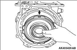
21.Remove the reverse
overdrive clutch.
|

|
22.Remove the overdrive
clutch hub and thrust bearing number 3.
|

|
23.Remove the thrust bearing
#4.
| note |
The thrust bearing #4
may be attached to the overdrive clutch
hub.
|
|

|
24.Remove the reverse sun
gear.
|

|
26.Remove the second brake
and return spring.
|

|
27.Remove the
low/reverse annulus gear.
|

|
28.Remove the pressure
plate, brake plates and brake discs.
|

|
29.Remove the thrust bearing
#7.
| note |
The thrust bearing #7
may be attached to the low/reverse annulus
gear.
|
|

|
31.Remove the reaction plate
and one brake disc.
|

|
33.Remove the brake plates,
brake discs, and pressure plate.
|

|
34.Remove the wave
spring.
|

|
35.Remove the snap ring and
center support.
|

|
36.Remove the thrust race
#8, thrust bearing #9 and output
flange.
| note |
The thrust race #8 may
be attached to the center support.
|
|

|
37.Remove the thrust bearing
#10 and underdrive clutch hub.
|

|
38.Remove the thrust bearing
#11 and underdrive clutch.
| note |
The thrust bearing #11
may be attached to the underdrive clutch
hub.
|
|

|
39.Remove the thrust bearing
#12.
| note |
The thrust bearing #12
may be attached to the underdrive
clutch.
|
|

|
40.Remove the output
shaft.
|

|
41.Remove the two large and
two small seal rings from the output shaft.
|

|
42.Remove the thrust bearing
#13 and bearing retainer.
| note |
The thrust bearing #13
may be attached to the output shaft
support.
|
|

|
43.Remove the eight output
shaft support mounting bolts, and then remove the output
shaft
support and gasket.
|
|
1.
| caution |
Never reuse a gasket.
|
Install a new gasket and output shaft
support.
2.Tighten the eight output shaft support
mounting bolts to the specified torque of 23 ±3
N·m.
|

|
3.
| caution |
Make sure the thrust bearing
is mounted in the correct direction.
|
Install the bearing retainer and thrust bearing
#13 onto the output shaft.
Symbol
|
O.D.
mm
|
I.D.
mm
|
Thickness
mm
|
Symbol
|
O.D.
mm
|
I.D.
mm
|
Thickness
mm
|
#1
|
48.9
|
37
|
1.4
|
#6
|
57
|
38.5
|
4.12
|
1.6
|
#7
|
70
|
48.8
|
4.0
|
1.8
|
#8
|
73
|
60
|
1.6
|
2.0
|
1.8
|
2.2
|
2.0
|
2.4
|
2.2
|
2.6
|
#9
|
71.45
|
57
|
2.81
|
#2
|
59
|
37
|
2.8
|
#10
|
72
|
48.25
|
4.6
|
#3
|
57
|
38.5
|
4.12
|
#11
|
53
|
34.7
|
4.01
|
#4
|
57
|
38.5
|
4.12
|
#12
|
57
|
38.5
|
4.12
|
#5
|
55.4
|
38.5
|
3.31
|
#13
|
58
|
37.5
|
4.8
|
|
|
4.Install new seal rings
(two large pieces and two small pieces) onto the output
shaft.
|
|
5.Install the output shaft
into the output shaft support.
|

|
6.
| caution |
Make sure thrust bearing
#12 is mounted in the
correct direction.
|
Apply Vaseline or petroleum jelly on the thrust
bearing #12, and then install
on the front end of the output shaft.
|

|
7.Install the underdrive
clutch.
|


|
8.
| caution |
Make sure thrust bearing
#11 is mounted in the
correct direction.
|
Apply Vaseline or petroleum jelly on the thrust
bearing #11, and then install
on the front end of the underdrive clutch retainer.
|

|
9.Install the underdrive
clutch hub.
|


|
10.
| caution |
Make sure thrust bearing
#10 is mounted in the
correct direction.
|
Apply Vaseline or petroleum jelly on the thrust
bearing #10, and then install
it on the underdrive clutch hub.
|

|
11.Install the output
flange.
|


|
12.
| caution |
Make sure thrust bearing
#9 is mounted in the
correct direction.
|
Apply Vaseline or petroleum jelly on the thrust
bearing #9, and then install
on the output flange.
|

|
13.
| caution |
Measure and record the
thickness of the thrust race #8
to be assembled.
|
Apply Vaseline or blue petroleum jelly on the thrust
race #8 being used, and
then install it on the rear side of the center
support.
|
|
14.
| caution |
- Install the center support so that the
oil
holes shown in the illustration face the
lower side of the transmission
case.
- Make sure that the thrust race #8
attached to the rear side of the center
support does not fall off.
|
Install the center support.
|

|
15.Remove the two output
shaft support mounting bolts.
16.Using the two
removed bolts, install special tool Bearing installer
stopper (MB991603)
to the specified torque of 23 ± 3 N·m.
|


|
17.Select the thrust race
#8 with the following procedure:
(1)
Fix a dial gauge to special tool Bearing installer stopper
(MB991603).
(2)
Push the output shaft, and the output flange in alternately,
and then measure the end
play of output shaft.
|
|
| note |
- When pushing the output
shaft in, take care that the
center support does not
move.
- When pushing the output
flange in, use the special
tool Oil seal installer
(MD998029).
|
|
(3)
Reinstall by selecting the thrust race #8 installed by
the procedure (13) so
that the end play of output shaft becomes the standard
value.
|
|
| note |
Refer to the
thickness recorded in step
13.
|
|
Standard value: 0.25 - 0.71
mm
(4)
Measure the end play again, and confirm that it is within
the standard value.
|
|
| note |
Carry this step
out with special tool Bearing
installer stopper (MB991603) and
dial gauge
installed.
|
|
|


|
18.Using the following
steps, select the snap ring for fixing the center
support.
(1)
Install the snap ring used for fixing the center support
used.
(2)
After pushing the output shaft, and the center support in
alternately, and then measure
the end play of center support.
|
|
| note |
When pushing the
output shaft in, be sure to push
them in to the point where the
center
support touches the snap
ring.
|
|
(3)
Select the snap ring for fixing the center support installed
in step 18 (1) so that the
end play of the center support is at the standard value.
Then, reassemble.
Standard value: 0 -
0.16 mm
(4)
Measure the end play again, and confirm that it is within
the standard value.
|


|
19.Using the following
steps, select the snap ring for adjusting the brake reaction
plate
end play and second brake end play, and the pressure plate
for adjusting the low/reverse
brake end play.
(1)
Install the wave spring onto the low/reverse brake
piston.
(2)
Install special tool Clearance dummy plate (MB991632) onto
the position shown in the illustration
instead of the pressure plate for the low/reverse
brake. Install the six brake disc,
five brake plate and snap ring.
(3)
|
|
| caution |
Pay close
attention to the assembly direction
of the reaction
plate.
|
|
Install the reaction plate and snap ring that was
used.
(4)
Install a dial gauge onto special tool Dial gauge extension
(MD998913) so that the
end contacts the brake reaction plate. Measure the end play
by moving special tool Clearance
dummy plate (MB991632).
(5)
Select the snap ring installed in step 19 (3) so that the
end play is within the standard
value. Then, reassemble.
Standard value: 0
- 0.16 mm
(6)
Measure the end play again, and confirm that it is within
the standard value.
(7)
|
|
| caution |
Pay close
attention to the shape and assembly
direction
of the brake plate A installation.
|
|
Next, install special tool Clearance dummy plate
(MB991632) instead of the pressure plate
for the second brake. Install the four brake discs and three
brake plates.
(8)
Install the return spring, second brake and snap
ring.
(9)
Install a dial gauge onto special tool Dial gauge extension
(MD998913) so the end contacts
the special tool. Move special tool Clearance dummy plate
(MB991632) and measure the moving
amount. Select a pressure plate with a thickness that
corresponds to the measured moving amount
from the following table.
Standard value
(reference): 1.49 - 1.95 mm
PRESSURE
PLATE FOR SECOND BRAKE
|
|
Moving amount
mm
|
Pressure
plate
|
Thickness
mm
|
identification
symbol
|
1.2 or more -
less than 1.4
|
1.6
|
F
|
1.4 or more -
less than 1.6
|
1.8
|
E
|
1.6 or more -
less than 1.8
|
2.0
|
D
|
1.8 or more -
less than 2.0
|
2.2
|
C
|
2.0 or more -
less than 2.2
|
2.4
|
B
|
2.2 or more -
less than 2.4
|
2.6
|
A
|
2.4 or more -
less than 2.6
|
2.8
|
0
|
2.6 or more -
less than 2.8
|
3.0
|
1
|
|
(10)
Remove the snap ring, second brake, return spring and
special tool Clearance dummy
plate (MB991632) installed in step (8).
(11)
Install the pressure plate selected in step (9), and install
the return spring, second
brake and snap ring again.
(12)
Install a dial gauge onto special tool Dial gauge extension
(MD998913) so the end contacts
the special tool. Move special tool Clearance dummy plate
(MB991632) and measure the moving
amount. Select a pressure plate with a thickness that
corresponds to the measured moving amount
from the following table.
End play standard
value (reference): 1.65 - 2.11 mm
<4M40>
PRESSURE PLATE FOR LOW/REVERSE
BRAKE
|
|
Moving amount
mm
|
Pressure
plate
|
Thickness
mm
|
Identification
symbol
|
1.5 or more -
less than 1.7
|
1.8
|
E
|
1.7 or more -
less than 1.9
|
2.0
|
D
|
1.9 or more -
less than 2.1
|
2.2
|
C
|
2.1 or more -
less than 2.3
|
2.4
|
B
|
2.3 or more -
less than 2.5
|
2.6
|
A
|
2.5 or more -
less than 2.7
|
2.8
|
0
|
2.7 or more -
less than 2.9
|
3.0
|
1
|
|
End play standard value (reference): 1.35
- 1.81 mm <6G72>
PRESSURE PLATE
FOR LOW/REVERSE BRAKE
|
|
Moving amount
mm
|
Pressure
plate
|
Thickness
mm
|
Identification
symbol
|
1.2 or more -
less than 1.4
|
1.8
|
E
|
1.4or more -
less than 1.6
|
2.0
|
D
|
1.6 or more -
less than 1.8
|
2.2
|
C
|
1.8 or more -
less than 2.0
|
2.4
|
B
|
2.0 or more -
less than 2.2
|
2.6
|
A
|
2.2 or more -
less than 2.4
|
2.8
|
0
|
2.4 or more -
less than 2.6
|
3.0
|
1
|
|
(13)
Remove the parts installed in steps 19 (1) to (12).
|

|
20.
| caution |
Make sure thrust bearing
#7 is mounted in the
correct direction.
|
Apply Vaseline or petroleum jelly on the thrust
bearing #7, and then install
on the rear side of the low/reverse annulus
gear.
|
|
21.
| caution |
Make sure that thrust bearing
#7 attached to
the rear side of the low/reverse annulus
gear does not fall off.
|
Install the low/reverse annulus gear.
|
|
22.Install the reverse sun
gear.
|

|
23.Install the wave spring
to the low/reverse brake piston.
|

|
24.Install the pressure
plate, six brake disc and five brake plate selected in step
19 (12).
|

|
25.Install the snap
ring.
|

|
26.
| caution |
Make sure the reaction plate
in the proper direction.
|
Install the reaction plate.
|

|
27.Install the snap ring
selected in step 19 (5).
|

|
28.
| caution |
Make sure the brake plate
(reaction plate side) is installed in
the proper direction.
|
Install the brake disc, brake plate and pressure
plate selected in step 19 (9).
|


|
29.
| caution |
Install the return spring end
coil side so that it faces
the back of the transmission. (Only for one side
end coil type)
|
Install the return spring and second brake.
|

|
30.Install the snap
ring.
|

|
31.
| caution |
Make sure thrust bearing
#4 is installed in
the proper direction.
|
Apply Vaseline or petroleum jelly on the thrust
bearing #4, and then install
on the reverse sun gear.
|

|
32.
| caution |
Make sure thrust bearing
#3 is mounted in the
correct direction.
|
Apply Vaseline or petroleum jelly on the thrust
bearing #3, and then install
on the overdrive clutch hub.
33.Install the
overdrive clutch hub.
|


|
34.
| caution |
Make sure thrust bearing
#2 is mounted in the
correct direction.
|
Install the reverse and overdrive clutch.
|

|
35.Apply Vaseline or
petroleum jelly on the thrust bearing #2, and then
install
on the reverse and overdrive clutch.
|

|
36.Apply Vaseline or
petroleum jelly on the thrust race #1 being used, and
then
install on the oil pump.
|

|
37.
| caution |
Never reuse a gasket.
|
Install special tools Guide (MD998412) at the
position shown in the illustration, and
using this as a guide, install the oil pump and
gasket.
38.Tighten the ten oil pump mounting bolts
to the specified torque of 23 ± 3
N·m.
|

|
39.Use the special tool Dial
gauge support (MD998316), set a dial gauge as shown in the
illustration.
Measure the end play of the input shaft, and select the
thrust race installed in step 36 so
that the end play is at the standard value. Then,
reassemble.
Standard value: 0.25 - 0.81
mm
40.Measure the end play again, and
confirm that it is within the standard value.
|

|
41.
| caution |
Evenly squeeze out the sealant
so that it is not insufficient or
excessive.
|
Apply the sealant on the converter housing.
Specified sealant:
Mitsubishi Part No.
MD997740 or equivalent
|
|
42.Install the converter
housing.
43.Tighten the eight converter housing
mounting bolts to the specified torque of 48 ± 6
N·m.
|

|
44.Install the parking
roller rod to the detent lever.
|

|
45.Install two new O-rings
to the manual control shaft, and assemble onto the
transmission
case together with the detent lever and parking roller
rod.
|

|
47.Hammer in so that the
slit section of the spring valve is perpendicular to the
axial direction
of the manual control shaft.
|

|
48.Install a new seal ring
onto each accumulator piston.
49.Install each
accumulator piston and spring.
| note |
Identification colors are
applied on the spring as shown below. Assemble
following this
table.
|
| note |
Install the accumulator
pistons to the original positions following the
identification
tags attached when removed.
|
|
|
No.
|
Name
|
Identification
paint application
position
|
1
|
For overdrive
clutch
|
None
|
2
|
For second
brake
|
Inner
|
Applied on all
surfaces including both
ends
|
Outer
|
Applied on half of
surface including both ends
|
3
|
For low/reverse
brake
|
Inner
|
Applied on half of
surface including both ends
|
Outer
|
Applied on entire
surface of one side
|
4
|
For underdrive
clutch
|
Inner
|
Applied on half of
surface including both ends
|
Outer
|
Applied on half of
surface including both ends
|
|
|
|
50.
| caution |
Pay close attention to the
installation direction of
the oil seal.
|
Install the oil strainer and two new oil seals.
Install the oil seals so that the notched
section is oriented as shown in the illustration.
|
|
51.Install the solenoid
valve harness, and then secure the snap ring into connector
groove.
| note |
Install the harness so that it
is oriented as shown in the
illustration.
|
|
|
52.Install the new O-ring
into the transmission case at the position shown in the
illustration.
|

|
53.Install the valve body
while inserting of Control shaft into the detent lever
groove.
|

|
54.Tighten the twenty valve
body mounting bolts to the specified torque of 11 ± 1
N·m.
|
|
Bolt
|
Length
mm
|
A
|
25
|
B
|
30
|
C
|
40
|
D
|
45
|
E
|
55
|
|
|

|
55.Install the oil
temperature sensor.
|
|
56.Connect the connector to
the valve body.
|
|
57.Install the detent
spring.
58.Tighten the detent spring mounting bolt
to the specified torque of 6.0 ± 1.0
N·m.
|
|
59.Install the oil filter
and a new O-ring.
|

|
60.Install the
magnet.
61.
| caution |
Evenly squeeze out the sealant
so that it is not insufficient or
excessive.
|
Apply the sealant or equivalent on the oil
pan.
Specified sealant:
Mitsubishi Part No.
MD997740 or equivalent
|

|
62.Install the oil
pan.
63.Tighten the oil pan mounting bolts to the
specified torque of 11 ± 1 N·m.
|

|
64.
| caution |
- Install the parking gear so that the
side
without the spline cut faces the
transmission side.
- Heat the parking gear to 160 - 180
°C and shrink fit up to the
stepped section of the output shaft. Do
not heat for longer than necessary at
this time.
|
Install the parking gear and snap ring.
|
|
65.Install the inhibitor
switch and manual control lever.
|
|
66.Install the output shaft
speed sensor.
|
|
67.Install the input shaft
speed sensor.
|

|
68.
| caution |
Apply ATF to the oil pump
drive hub before installing
the torque converter. Be careful not to damage
the oil seal lip when installing the torque
converter.
|
Install the torque converter, and secure it so that
the dimension (A) indicated in the
illustration meets the reference
value.
Reference value: 20.9 mm
|


