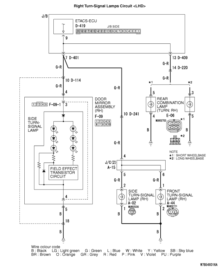
Inspection Procedure 8: Any of the Turn-signal Lamps does not
Illuminate.
| caution |
Whenever the ECU is replaced, ensure that
the input and output signal circuits are normal.
|


COMMENTS ON TROUBLE SYMPTOM
If any of the turn-signal lamp
does not illuminate normally, wiring harness connector(s) or the bulb
may be defective.
PROBABLE CAUSES
- Malfunction of the turn-signal lamp bulb
- Damaged harness wires and connectors
DIAGNOSIS PROCEDURE
STEP 1. Confirm which turn-signal lamp is
defective.
Q.
Which turn-signal lamp fails to illuminate correctly?
YES
(All of the turn-signal lamps illuminate normally) : The procedure is
complete.
NO (Only the front turn-signal lamps does not
illuminate normally) : Go to Step
2.
: Go to Step
2.
NO (Only the side turn-signal lamps (in door mirror type) does
not illuminate normally) : Go to Step
6.
NO (Only the side turn-signal lamps (fender panel attachment
type) does not illuminate normally) : Go to Step
11.
NO (Only the rear turn-signal lamps does not illuminate
normally) :
Go to Step 15.
STEP 2. Connector check: A-44
front turn-signal lamp (RH) or A-18 front turn-signal lamp (LH)
connector.
Q.
Is the check result normal?
 Go to Step
3.
Go to Step
3.
 Repair the defective
connector.
Repair the defective
connector.
STEP 3. Check the bulb(s) of the
turn-signal lamps.
Check the bulb(s) of the defective
lamp.
Q.
Is the check result normal?
Go to Step
4.
Replace the bulb(s)
of the defective lamp.
STEP 4. Resistance
measurement at the A-44 front turn-signal lamp (RH) or A-18 front
turn-signal lamp (LH) connector.
|
|
(1)Disconnect the connector, and measure at the
wiring harness side.
|
|
|
(2)Measure the resistance between the defective lamp
connector terminal and body earth.
- Resistance between A-44 front turn-signal lamp (RH)
connector terminal No.2 and body earth
- Resistance between A-18 front turn-signal lamp (LH)
connector terminal No.2 and body earth
OK: Continuity exists (2 Ω or
less)
|
Q.
Is the check result normal?
Go to Step 19.
Go to Step
5.
STEP 5. Check the wiring harness from
A-44 front turn-signal lamp (RH) connector terminal No.2 and body
earth or A-18 front turn-signal lamp (LH) connector terminal No.2
and body earth.
- Check the earth wires for open circuit.
Q.
Is the check result normal?
The trouble can be an
intermittent malfunction (Refer to GROUP 00 - How to Cope with
Intermittent Malfunction  ).
).
Repair the wiring
harness.
STEP 6. Connector check: F-09-1
side turn-signal lamp (RH) or F-04-1 side turn-signal lamp (LH)
connector.
Q.
Is the check result normal?
Go to Step
7.
Repair the defective
connector.
STEP 7. Resistance measurement at
the F-09-1 side turn-signal lamp (RH) or F-04-1 side turn-signal
lamp (LH) connector.
|
|
(1)Disconnect the connector, and measure at the
wiring harness side.
|
|
|
(2)Measure the resistance between the defective lamp
connector terminal and body earth.
- Resistance between F-09-1 side turn-signal lamp (RH)
connector terminal No.4 and body earth
- Resistance between F-04-1 side turn-signal lamp (LH)
connector terminal No.4 and body earth
OK: Continuity exists (2 Ω or
less)
|
Q.
Is the check result normal?
Go to Step 22.
Go to Step
8.
STEP 8. Connector check: F-09 door mirror
assembly (RH) or F-04 door mirror assembly (LH)
connector.
Q.
Is the check result normal?
Go to Step
9.
Repair the defective
connector.
STEP 9. Resistance measurement at
the F-09 door mirror assembly (RH) or F-04 door mirror assembly (LH)
connector.
|
|
(1)Disconnect the connector, and measure at the
wiring harness side.
|
|
|
(2)Measure the resistance between the defective lamp
connector terminal and body earth.
- Resistance between F-09 door mirror assembly (RH)
connector terminal No.5 and body earth
- Resistance between F-04 door mirror assembly (LH)
connector terminal No.5 and body earth
OK: Continuity exists (2 Ω or
less)
|
Q.
Is the check result normal?
Repair the wiring harness in the
door mirror assembly.
Go to Step 10.
STEP 10. Check the wiring harness from F-09 door
mirror assembly (RH) or F-04 door mirror assembly (LH) connector
terminal No.5 and body earth.
| note |
Prior to the wiring harness inspection,
check intermediate connector D-114 <side turn-signal
lamp (RH)>, D-133 <side turn-signal lamp
(LH)>, and repair if necessary.
|
- Check the earth wires for open circuit.
Q.
Is the check result normal?
The trouble can be an
intermittent malfunction (Refer to GROUP 00 - How to Cope with
Intermittent Malfunction ).
Repair the wiring
harness.
STEP 11. Connector check: A-02 side
turn-signal lamp (RH) or A-04 side turn-signal lamp (LH)
connector.
Q.
Is the check result normal?
Go to Step
12.
Repair the defective
connector.
STEP 12. Check the bulb(s) of the
turn-signal lamps.
Check the bulb(s) of the defective
lamp.
Q.
Is the check result normal?
Go to Step
13.
Replace the bulb(s)
of the defective lamp.
STEP 13. Resistance
measurement at the A-02 side turn-signal lamp (RH) or A-04 side
turn-signal lamp (LH) connector.
|
|
(1)Disconnect the connector, and measure at the
wiring harness side.
|
|
|
(2)Measure the resistance between the defective lamp
connector terminal and body earth.
- Resistance between A-02 side turn-signal lamp (RH)
connector terminal No.1 and body earth
- Resistance between A-04 front turn-signal lamp (LH)
connector terminal No.1 and body earth
OK: Continuity exists (2 Ω or
less)
|
Q.
Is the check result normal?
Go to Step 25.
Go to Step
14.
STEP 14. Check the wiring harness from
A-02 side turn-signal lamp (RH) connector terminal No.1 and body
earth or A-04 side turn-signal lamp (LH) connector terminal No.1 and
body earth.
- Check the earth wires for open circuit.
Q.
Is the check result normal?
The trouble can be an
intermittent malfunction (Refer to GROUP 00 - How to Cope with
Intermittent Malfunction ).
Repair the wiring
harness.
STEP 15. Connector check: E-06 rear
combination lamp (TURN: RH) or E-12 rear combination lamp (TURN: LH)
connector.
Q.
Is the check result normal?
Go to Step
16.
Repair the defective
connector.
STEP 16. Check the bulb(s) of the
turn-signal lamps.
Check the bulb(s) of the defective
lamp.
Q.
Is the check result normal?
Go to Step
17.
Replace the bulb(s)
of the defective lamp.
STEP 17. Resistance
measurement at the E-06 rear combination lamp (TURN: RH) or E-12
rear combination lamp (TURN: LH) connector.
|
|
(1)Disconnect the connector, and measure at the
wiring harness side.
|
|
|
(2)Measure the resistance between the defective lamp
connector terminal and body earth.
- Resistance between E-06 rear combination lamp (TURN: RH)
connector terminal No.4 and body earth <Short
wheelbase>
- Resistance between E-06 rear combination lamp (TURN: RH)
connector terminal No.5 and body earth <Long
wheelbase>
- Resistance between E-12 rear combination lamp (TURN: LH)
connector terminal No.4 and body earth <Short
wheelbase>
- Resistance between E-12 rear combination lamp (TURN: LH)
connector terminal No.5 and body earth <Long
wheelbase>
OK: Continuity exists (2 Ω or
less)
|
Q.
Is the check result normal?
Go to Step 28.
Go to Step
18.
STEP 18. Check the wiring harness from
E-06 rear combination lamp (TURN: RH) connector terminal No.4
<Short wheelbase>, E-06 rear combination lamp (TURN: RH)
connector terminal No.5 <Long wheelbase>, E-12 rear
combination lamp (TURN: LH) connector terminal No.4 <Short
wheelbase>, E-12 rear combination lamp (TURN: LH) connector
terminal No.5 <Long wheelbase> and body
earth.
- Check the earth wires for open circuit.
Q.
Is the check result normal?
The trouble can be an
intermittent malfunction (Refer to GROUP 00 - How to Cope with
Intermittent Malfunction ).
Repair the wiring
harness.
STEP 19. Connector check: D-419
ETACS-ECU connector
Q.
Is the check result normal?
Go to Step
20.
Repair the defective
connector.
STEP 20. Check the wiring harness
from the A-44 front turn-signal lamp (RH) connector terminal No.1 to
D-419 ETACS-ECU connector terminal No.9 or A-18 front turn-signal
lamp (LH) connector terminal No.1 to D-419 ETACS-ECU connector
terminal No.14.
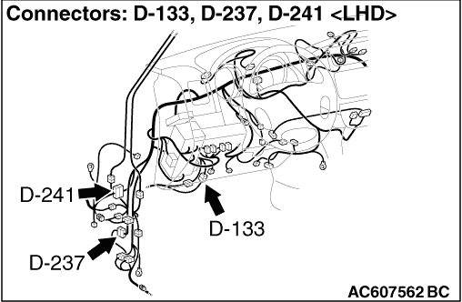
| note |
Prior to the wiring harness inspection,
check intermediate connector D-241, joint connector A-15
<front turn-signal lamp (RH)> or A-14
<front turn-signal lamp (LH)> and junction block
connector D-401, and repair if necessary.
|
- Check the output lines for open circuit.
Q.
Is the check result normal?
Go to Step
21.
Repair the wiring
harness.
STEP 21. Retest the
system.
Check that the front turn-signal lamps illuminate
normally.
Q.
Is the check result normal?
The trouble can be an
intermittent malfunction (Refer to GROUP 00 - How to Cope with
Intermittent Malfunction ).
Replace the front turn-signal
lamp.
STEP 22. Connector check: D-419
ETACS-ECU connector
Q.
Is the check result normal?
Go to Step
23.
Repair the defective
connector.
STEP 23. Check the wiring harness
from the F-09-1 side turn-signal lamp (RH) connector terminal No.3
to D-419 ETACS-ECU connector terminal No.9 or F-04-1 side
turn-signal lamp (LH) connector terminal No.3 to D-419 ETACS-ECU
connector terminal No.14.
| note |
Prior to the wiring harness inspection,
check intermediate connector D-114 <side turn-signal
lamp (RH)> or D-133 <side turn-signal lamp
(LH)> and junction block connector D-401, and repair
if necessary.
|
- Check the output lines for open circuit.
Q.
Is the check result normal?
Go to Step
24.
Repair the wiring
harness.
STEP 24. Retest the
system.
Check that the side turn-signal lamps illuminate
normally.
Q.
Is the check result normal?
The trouble can be an
intermittent malfunction (Refer to GROUP 00 - How to Cope with
Intermittent Malfunction ).
Replace the side turn-signal
lamp.
STEP 25. Connector check: D-419
ETACS-ECU connector
Q.
Is the check result normal?
Go to Step
26.
Repair the defective
connector.
STEP 26. Check the wiring harness
from the A-02 side turn-signal lamp (RH) connector terminal No.2 to
D-419 ETACS-ECU connector terminal No.9 or A-04 side turn-signal
lamp (LH) connector terminal No.2 to D-419 ETACS-ECU connector
terminal No.14.
| note |
Prior to the wiring harness inspection,
check intermediate connector D-241, joint connector A-15
<side turn-signal lamp (RH)> or A-14 <side
turn-signal lamp (LH)> and junction block connector
D-401, and repair if necessary.
|
- Check the output lines for open circuit.
Q.
Is the check result normal?
Go to Step
27.
Repair the wiring
harness.
STEP 27. Retest the
system.
Check that the side turn-signal lamps illuminate
normally.
Q.
Is the check result normal?
The trouble can be an
intermittent malfunction (Refer to GROUP 00 - How to Cope with
Intermittent Malfunction ).
Replace the side turn-signal
lamp.
STEP 28. Connector check: D-419
ETACS-ECU connector
Q.
Is the check result normal?
Go to Step
29.
Repair the defective
connector.
STEP 29. Check the wiring harness
from the E-06 rear combination lamp (TURN: RH) connector terminal
No.5 <Short wheelbase>, E-06 rear combination lamp
(TURN: RH) connector terminal No.3 <Long wheelbase> to
D-419 ETACS-ECU connector terminal No.9 or E-12 rear combination
lamp (TURN: LH) connector terminal No.5 <Short
wheelbase>, E-12 rear combination lamp (TURN: LH) connector
terminal No.3 <Long wheelbase> to D-419 ETACS-ECU
connector terminal or No.14.
| note |
<L.H. drive vehicles> Prior to
the wiring harness inspection, check intermediate connector
D-220 <rear combination lamp (TURN: RH)>, D-237
<rear combination lamp (TURN: LH)> and junction
block connector D-409 <rear combination lamp (TURN:
RH)>, D-405 <rear combination lamp (TURN:
LH)>, and repair if necessary.
|
| note |
<R.H. drive vehicles> Prior to
the wiring harness inspection, check intermediate connector
D-237 <rear combination lamp (TURN: LH)> and
junction block connector D-422 <rear combination lamp
(TURN: RH)>, D-401 <rear combination lamp (TURN:
LH)>, and repair if necessary.
|
- Check the output lines for open circuit.
Q.
Is the check result normal?
Go to Step
30.
Repair the wiring
harness.
STEP 30. Retest the
system.
Check that the rear turn-signal lamps illuminate
normally.
Q.
Is the check result normal?
The trouble can be an
intermittent malfunction (Refer to GROUP 00 - How to Cope with
Intermittent Malfunction ).
Replace the rear turn-signal
lamp assembly.