


COMMENTS ON TROUBLE SYMPTOM |
| If the front passenger’s or
rear power window does not work by means of the respective
power window sub switch, the power window sub switch or the
power window motor may be defective. |
PROBABLE CAUSES <LH DRIVE VEHICLES> |
|
PROBABLE CAUSES <RH DRIVE VEHICLES> |
|
DIAGNOSIS PROCEDURE |
Step 1. Check the power window main switch. |
| Check that the power window lock
switch is turned off. |
Q.
Is the check result normal?
|
 Go to Step
2. Go to Step
2. |
|
 Turn off the power
window lock switch. Turn off the power
window lock switch. |
|
Step 2. Connector check: F-05 power window main switch connector |
  |
Q.
Is the check result normal?Go to Step
3.Repair
the connector. |
Step 3. Check the power window main switch |
Check that the power window main
switch works normally. Refer to GROUP 42 - Door  . . |
Q.
Is the check result normal?
|
| Go to Step
4. |
|
| Replace the power
window main switch. |
|
Step 4. Determine a trouble spot. |
Q.
Which power window does not work?
|
Front passenger’s door
<LH drive vehicles> : Go to
Step 5. : Go to
Step 5. |
|
| Front passenger’s door
<RH drive vehicles> : Go to
Step 13. |
|
| Rear right door : Go to
Step 21. |
|
| Rear left door : Go to
Step 29. |
|
Step 5. Connector check: F-15 power window sub switch (front: RH) connector and F-16 power window motor (front: RH) connector |
 |
Q.
Is the check result normal?Go to Step
6.Repair
the connector. |
Step 6. Check the power window sub switch (front: RH) |
| Check that the power window sub
switch (front: RH) works normally. Refer to GROUP 42 -
Door . |
Q.
Is the check result normal?
|
| Go to Step
7. |
|
| Replace the power
window sub switch (front: RH). |
|
Step 7. Check the power window motor (front: RH) |
| Check that the power window motor
(front: RH) works normally. Refer to GROUP 42 - Door
. |
Q.
Is the check result normal?
|
| Go to Step
8. |
|
| Replace the power
window motor (front: RH). |
|
Step 8. Voltage measurement at F-15 power window sub switch (front: RH) connector. |
 |
(1)Disconnect the connector, and
measure at the wiring harness side. (2)Turn the ignition switch to the ON position. |
 |
(3)Voltage between terminal 6 and
body earth OK: System voltage Q.
Is the check result normal?Go to Step
11.Go to Step
9. |
Step 9. Connector check: C-217 power window relay connector |
 |
Q.
Is the check result normal?Go to Step
10.Repair
the connector. |
Step 10. Check the wiring harness from F-15 power window sub switch (front: RH) connector terminal No.6 to C-217 power window relay connector terminal No.4. |
 |
 |
Q.
Is the check result normal?The trouble can be
an intermittent malfunction (Refer to GROUP 00 - How
to Cope with Intermittent Malfunction ).Repair the wiring
harness. |
Step 11. Check the wiring harness from F-16 power window motor (front: RH) connector terminal Nos. 1 and 2 to F-15 power window sub switch (front: RH) connector terminal Nos. 4 and 7. |
|
Q.
Is the check result normal?Go to Step
12.Repair
the wiring harness. |
Step 12. Check the wiring harness from F-05 power window main switch connector terminal Nos. 12 and 14 to F-15 power window sub switch (front: RH) connector terminal Nos. 8 and 5. |
|
 |
Q.
Is the check result normal?The trouble can be
an intermittent malfunction (Refer to GROUP 00 - How
to Cope with Intermittent Malfunction ).Repair the wiring
harness. |
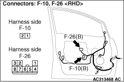
Step 13. Connector check: F-26 power window sub switch (front: LH) connector and F-10 power window motor (front: LH) connector |
 |
Q.
Is the check result normal?Go to Step
14.Repair
the connector. |
Step 14. Check the power window sub switch (front: LH) |
| Check that the power window sub
switch (front: LH) works normally. Refer to GROUP 42 -
Door . |
Q.
Is the check result normal?
|
| Go to Step
15. |
|
| Replace the power
window sub switch (front: LH). |
|
Step 15. Check the power window motor (front: LH) |
| Check that the power window motor
(front: LH) works normally. Refer to GROUP 42 - Door
. |
Q.
Is the check result normal?
|
| Go to Step
16. |
|
| Replace the power
window motor (front: LH). |
|
Step 16. Voltage measurement at F-26 power window sub switch (front: LH) connector. |
 |
(1)Disconnect the connector, and
measure at the wiring harness side. (2)Turn the ignition switch to the ON position. |
 |
(3)Voltage between terminal 6 and
body earth OK: System voltage Q.
Is the check result normal?Go to Step
19.Go to Step
17. |
Step 17. Connector check: C-217 power window relay connector |
 |
Q.
Is the check result normal?Go to Step
18.Repair
the connector. |
Step 18. Check the wiring harness from F-26 power window sub switch (front: LH) connector terminal No.6 to C-217 power window relay connector terminal No.4. |
 |
 |
Q.
Is the check result normal?The trouble can be
an intermittent malfunction (Refer to GROUP 00 - How
to Cope with Intermittent Malfunction ).Repair the wiring
harness. |
Step 19. Check the wiring harness from F-10 power window motor (front: LH) connector terminal Nos. 1 and 2 to F-26 power window sub switch (front: LH) connector terminal Nos. 4 and 7. |
|
Q.
Is the check result normal?Go to Step
20.Repair
the wiring harness. |
Step 20. Check the wiring harness from F-05 power window main switch connector terminal Nos. 7 and 9 to F-26 power window sub switch (front: RH) connector terminal Nos. 8 and 5. |
|
 |
Q.
Is the check result normal?The trouble can be
an intermittent malfunction (Refer to GROUP 00 - How
to Cope with Intermittent Malfunction ).Repair the wiring
harness. |
Step 21. Connector check: F-18 power window sub switch (rear: RH) connector and F-19 power window motor (rear: RH) connector |
 |
Q.
Is the check result normal?Go to Step
22.Repair
the connector. |
Step 22. Check the power window sub switch (rear: RH) |
| Check that the power window sub
switch (rear: RH) works normally. Refer to GROUP 42 -
Door . |
Q.
Is the check result normal?
|
| Go to Step
23. |
|
| Replace the power
window sub switch (rear: RH). |
|
Step 23. Check the power window motor (rear: RH) |
| Check that the power window motor
(rear: RH) works normally. Refer to GROUP 42 - Door . |
Q.
Is the check result normal?
|
| Go to Step
24. |
|
| Replace the power
window motor (rear: RH). |
|
Step 24. Voltage measurement at F-18 power window sub switch (rear: RH) connector. |
 |
(1)Disconnect the connector, and
measure at the wiring harness side. (2)Turn the ignition switch to the ON position. |
 |
(3)Voltage between terminal 6 and
body earth OK: System voltage Q.
Is the check result normal?Go to Step
27.Go to Step
25. |
Step 25. Connector check: C-217 power window relay connector |
|
Q.
Is the check result normal?Go to Step
26.Repair
the connector. |
Step 26. Check the wiring harness from F-18 power window sub switch (rear: RH) connector terminal No.6 to C-217 power window relay connector terminal No.4. |
|
    |
Q.
Is the check result normal?The trouble can be
an intermittent malfunction (Refer to GROUP 00 - How
to Cope with Intermittent Malfunction ).Repair the wiring
harness. |
Step 27. Check the wiring harness from F-19 power window motor (rear: RH) connector terminal Nos. 1 and 2 to F-18 power window sub switch (rear: RH) connector terminal Nos. 4 and 7. |
|
Q.
Is the check result normal?Go to Step
28.Repair
the wiring harness. |
Step 28. Check the wiring harness from F-05 power window main switch connector terminal Nos. 4 and 6 to F-18 power window sub switch (rear: RH) connector terminal Nos. 8 and 5. |
|
   |
Q.
Is the check result normal?The trouble can be
an intermittent malfunction (Refer to GROUP 00 - How
to Cope with Intermittent Malfunction ).Repair the wiring
harness. |
Step 29. Connector check: F-02 power window sub switch (rear: LH) connector and F-01 power window motor (rear: LH) connector |
 |
Q.
Is the check result normal?Go to Step
30.Repair
the connector. |
Step 30. Check the power window sub switch (rear: LH) |
| Check that the power window sub
switch (rear: LH) works normally. Refer to GROUP 42 -
Door . |
Q.
Is the check result normal?
|
| Go to Step
31. |
|
| Replace the power
window sub switch (rear: LH). |
|
Step 31. Check the power window motor (rear: LH) |
| Check that the power window motor
(rear: LH) works normally. Refer to GROUP 42 - Door . |
Q.
Is the check result normal?
|
| Go to Step
32. |
|
| Replace the power
window motor (rear: LH). |
|
Step 32. Voltage measurement at F-02 power window sub switch (rear: LH) connector. |
 |
(1)Disconnect the connector, and
measure at the wiring harness side. (2)Turn the ignition switch to the ON position. |
 |
(3)Voltage between terminal 6 and
body earth OK: System voltage Q.
Is the check result normal?Go to Step
35.Go to Step
33. |
Step 33. C-217 power window relay connector |
|
Q.
Is the check result normal?Go to Step
34.Repair
the connector. |
Step 34. Check the wiring harness from F-02 power window sub switch (rear: LH) connector terminal No.6 to C-217 power window relay connector terminal No.4. |
|
 |
Q.
Is the check result normal?The trouble can be
an intermittent malfunction (Refer to GROUP 00 - How
to Cope with Intermittent Malfunction ).Repair the wiring
harness. |
Step 35. Check the wiring harness from F-01 power window motor (rear: LH) connector terminal Nos. 1 and 2 to F-02 power window sub switch (rear: LH) connector terminal Nos. 4 and 7. |
|
Q.
Is the check result normal?Go to Step
36.Repair
the wiring harness. |
Step 36. Check the wiring harness from F-05 power window main switch connector terminal Nos. 1 and 3 to F-02 power window sub switch (front: LH) connector terminal Nos. 8 and 5. |
|
 |
Q.
Is the check result normal?The trouble can be
an intermittent malfunction (Refer to GROUP 00 - How
to Cope with Intermittent Malfunction ).Repair the wiring
harness. |