
|
COMMENTS ON TROUBLE SYMPTOM |
| If the blower motor does not
operate, the blower motor circuit system may be
defective. |
PROBABLE CAUSES |
|
DIAGNOSIS PROCEDURE |
STEP 1. Check the operation of the heater control panel |
| Check that the A/C switch,
rear window defogger switch and outside/inside
air selection switch can operate. |
Q.
Is the check result normal?
|
YES <LHD> : INSPECTION
PROCEDURE 31: Refer to A/C-ECU power supply system
<LHD> . . |
|
| YES <RHD Except vehicles for
Hong Kong and Singapore> : INSPECTION PROCEDURE 32:
Refer to A/C-ECU power supply system <RHD Except
vehicles for Hong Kong and Singapore>. |
|
| YES <RHD Vehicles for Hong
Kong and Singapore> : INSPECTION PROCEDURE 33: Refer
to A/C-ECU power supply system <RHD Vehicles
for Hong Kong and Singapore>. |
|
 Repair the CAN bus
line (Refer to GROUP 54F- Troubleshooting .) Repair the CAN bus
line (Refer to GROUP 54F- Troubleshooting .) |
|
STEP 2. M.U.T.-III actuator test |
| Carry out the actuator test. (Refer
to ) |
|
Q.
Does the blower motor work normally?
|
 Go to Step
3. Go to Step
3. |
|
| Go to Step
4. |
|
STEP 3. Recheck the trouble symptom |
Q.
Is the check result normal?
|
| Intermittent
malfunction (GROUP 00 - How to Cope with Intermittent
Malfunction ). |
|
| Replace the air
conditioner control panel (A/C-ECU) or the blower
motor
(blower linear controller). |
|
STEP 4. Connector check: C-209 front blower relay connector |
   |
Q.
Is the check result normal?Go to Step
5.Repair
the connector. |
STEP 5. Check the blower relay. |
| Refer to GROUP 55, On-vehicle
Service - Power relay check . |
Q.
Is the blower relay in good condition?
|
| Go to Step
6. |
|
| Replace the blower
relay. |
|
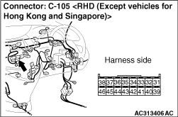
STEP 6. Connector check: C-13 front blower motor connector and C-105 A/C-ECU connector |
      |
Q.
Is the check result normal?Go to Step
7.Repair
the connector. |
STEP 7. Voltage measurement at the C-13 front blower motor controller connector. |
|
(1)Disconnect the connector, and
measure at the wiring harness side. (2)Turn the ignition switch to the ON position. |
 |
(3)Disconnect A/C-ECU
connector C-105, and earth terminal 45. |
 |
(4)measure the voltage between
terminal 1 and body earth. OK: System voltage Q.
Is the check result normal?Go to Step
14.Go to Step
8. |
STEP 8. Voltage measurement at C-209 front blower relay connector. |
|
(1)Remove the relay, and measure at
the junction block side. (2)Turn the ignition switch to the ON position. |
 |
(3)Voltage between terminal 3 and
body earth. OK: System voltage Q.
Is the check result normal?Go to Step
10.Go to Step
9. |
STEP 9. Check the wiring harness between C-209 front blower relay connector terminal No.3 and the ignition switch (IG2). |
   |
Q.
Is the check result normal?The trouble can be
an intermittent malfunction (Refer to GROUP 00, How to Cope
with Intermittent Malfunction .)Repair the wiring
harness. |
STEP 10. Voltage measurement at C-209 front blower relay connector. |
|
(1)Remove the relay, and measure at
the junction block side. (2)Turn the ignition switch to the ON position. |
 |
(3)Voltage between terminal 5 and
body earth. OK: System voltage Q.
Is the check result normal?Go to Step
12.Go to Step
11. |
STEP 11. Check the wiring harness between C-209 front blower relay connector terminal No.5 and fusible link (30). |
   |
   |
Q.
Is the check result normal?The trouble can be
an intermittent malfunction (Refer to GROUP 00, How to Cope
with Intermittent Malfunction ).Repair the wiring
harness. |
STEP 12. Check the wiring harness between C-209 front blower relay connector terminal No.4 and C-13 front blower motor connector terminal No.1. |
|
Q.
Is the check result normal?Go to Step
13.Repair
the wiring harness. |
STEP 13. Check the wiring harness between C-209 front blower relay connector terminal No.1 and C-105 A/C-ECU connector terminal No.45. |
   |
Q.
Is the check result normal?The trouble can be
an intermittent malfunction (Refer to GROUP 00, How to Cope
with Intermittent Malfunction ).Repair the wiring
harness. |
STEP 14. Check the front blower motor |
| Refer to . |
Q.
Is the check result normal?
|
| Go to Step
15. |
|
| Replace the
outside/inside air selection damper control
motor. |
|
STEP 15. Connector check: C-12 front power transistor controller connector |
   |
Q.
Is the check result normal?Go to Step
16.Repair
the connector. |
STEP 16. Resistance measurement at the C-12 front power transistor connector. |
|
(1)Disconnect the connector, and
measure at the wiring harness side. |
 |
(2)Continuity between terminal 2
and body earth OK: 2Ω or less Q.
Is the check result normal?Go to Step
18.Go to Step
17. |
STEP 17. Check the wiring harness between C-12 front power transistor connector terminal No.2 and body earth. |
|
Q.
Is the check result normal?The trouble can be
an intermittent malfunction (Refer to GROUP 00, How to Cope
with Intermittent Malfunction ).Repair the wiring
harness. |
STEP 18. Check the wiring harness between C-13 front blower motor connector terminal No.2 and C-12 front power transistor controller connector terminal No.4. |
   |
Q.
Is the check result normal?Go to Step
19.Repair
the wiring harness. |
STEP 19. Check the wiring harness between C-106 A/C-ECU connector (terminals 2 and 3) and C-12 front power transistor controller connector (terminals 3 and 1). |
   |
Q.
Is the check result normal?Go to Step
20.Repair
the wiring harness. |
STEP 20. Replace the front power transistor and recheck the trouble symptom |
| Check that the front blower motor
operates normally. |
Q.
Is the check result normal?
|
| This diagnosis is
complete. |
|
| Replace the
A/C-ECU. |
|