
|
1.In the following cases,
replace the timing chain.
(1)
With the timing chain tensioner removed from the cylinder
head, the protrusion A of the plunger (furthermost trace of
wear from tip) exceeds 26 mm.
(2)
With the engine running, the abnormal sound is generated by
the interference of the piston and valve.
|


|
2.Use the spare timing chain
kit (ME190551), and replace the timing chain according to
the following procedure.
Timing chain kit
(ME190551)
- (A): Timing chain
- (B): Timing chain tensioner
- (C): Timing chain tensioner gasket
- (D): Clip
- (E): Joint link
- (F): Mark plate (Blue)
- (G): Pin
(1)
Remove the power steering oil pipe mounting bolt for the
front of the cylinder head, and the rocker cover.
(2)
|
|
| caution |
Tighten the bolt
securely so that the special tool
fixture tool (MH063502) does not
come off by the rotational torque of
the timing chain.
|
|
Install the special tool (MH063502) to the cylinder
head, and tighten the bolt (M6 x 15 mm) securely.
(3)
Using the special tool pulley holder (MB991800) and crank
pulley holder (MB992100), turn the crankshaft pulley
clockwise and align the timing mark "0" of timing gear case
with the timing mark of crankshaft pulley to set the
cylinder No. 1 to the top dead centre of
compression.
|
|
| note |
If the hollow part
of the hexagonal part of the
camshaft is facing upward, the
cylinder No. 1 is at the top dead
centre of compression.
|
|
(4)
With the cylinder No. 1 being at the top dead centre of
compression, check that the timing marks of the camshaft
sprocket are set to the positions as shown.
(5)
Turn the crankshaft pulley clockwise, and stop the mark
plate (blue, single-plate side) of the timing chain to the
position as shown.
(6)
|
|
| caution |
Insert cloth or
similar materials into gap around
the timing chain to prevent the
parts from falling into the timing
gear case.
|
|
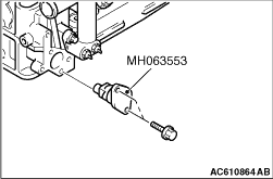
Remove the timing chain tensioner and timing chain
from the cylinder head, and install the special tool dummy
tensioner (MH063553) to the cylinder head.
(7)
|
|
| caution |
- If the pin cannot be pulled
out, insert the joint link
(E) of the timing chain kit
from the front of the
engine, and press and remove
the pin.
- Do not mix the removed mark
plate (blue, single-plate
side), pin, and chain plate
with the timing chain
kit.
|
|
Using the special tool chain disassembly tool
(MH063555), pull out the pin of the mark plate (blue,
single-plate side) of the timing chain, and remove the mark
plate (blue, single-plate side) and the chain plate.
(8)
Set the mark plates (blue, double-plate side) of the new
timing chain (A) of the timing chain kit to the front of the
engine, and connect the new timing chain (A) to the cut area
of the timing chain installed to the engine using the joint
link (E) and clip (D) of the timing chain kit.
(9)
Remove the cloth or similar materials around the timing
chain.
(10)
Slowly turn the crankshaft pulley clockwise to feed the
timing chain (A), and replace the timing chain installed to
the engine with the new timing chain (A).
(11)
When all the timing chain assembled to the engine is fed
out, stop at the position where the join link (E) and the
clip (D) are at the top of the camshaft sprocket.
(12)
Insert the cloth or similar materials into the gap around
the timing chain again, remove the joint link (E) and the
clip (D), and then remove the timing chain assembled to the
engine.
(13)
Remove the special tool (MH063553) from the cylinder
head.
(14)
To both ends of the timing chain (A) newly installed to the
engine, install the pin (G) of the timing chain kit from the
rear of the engine.
(15)
Install the mark plate (F) of the timing chain kit to the
punch of the special tool riveting (MH063559).
(16)
Align the pin section of pin (G) with the hole of mark plate
(F), and set the special tool (MH063559).
(17)
Tighten the set bolt of the special tool (MH063559) until it
stops.
(18)
Check that the pin protrusion of pin (G) is approximately 1
mm.
(19)
Set the special tool (MH063559) in reverse, and align the
mark plate (F) of timing chain (A) to the dice.
(20)
Tighten the set bolt of the special tool (MH063559) to the
tightening torque of approximately 29 N·m, and crimp
the pin tip of the pin (G).
(21)
Check if the width (b) of caulking part of pin section of
pin (G) is 2 mm.
(22)
Remove the punch around the timing chain, and then slightly
turn the crankshaft pulley clockwise. (To apply a load to
the timing chain)
(23)
Check that the plunger of the new timing chain tensioner (B)
of the timing chain kit is locked by the hook.
(24)
Install the timing chain tensioner (B) to the cylinder head
with the new timing chain tensioner gasket (C) of the timing
chain kit.
(25)
Turn the crankshaft pulley clockwise.
|
|
| note |
The hook of the
timing chain tensioner (B) is
removed when the crankshaft pulley
is turned clockwise.
|
|
(26)
When the cylinder No. 1 is at the top dead centre of
compression (the timing mark "0" of timing gear case is
aligned with the timing mark of crankshaft pulley), check
that the timing mark of camshaft sprocket is at the same
position as before the operation.
(27)
Remove the special tool (MH063502) from the cylinder head,
install the power steering oil pipe mounting bolt for the
front of the cylinder head, and the rocker cover.
|